Heat radiating device

A technology of heat dissipation device and heat dissipation hole, applied in the direction of cooling/ventilation/heating transformation, etc., can solve the problems of reducing the efficiency and life of components, unable to discharge heat energy, and bringing heat energy out of the product.

Inactive Publication Date: 2015-09-23
嘉兴匠欣印刷科技有限公司
View PDF7 Cites 0 Cited by
  • Summary
  • Abstract
  • Description
  • Claims
  • Application Information

AI Technical Summary

Problems solved by technology

[0002] Most of the 3C or consumer electronics products on the market today are designed towards the trend of thinner and lighter, and more and more functions are added in the limited space, which leads to higher and higher chip power consumption. As a result, a large amount of heat energy remains inside the product and cannot be discharged, which reduces the performance and life of the compo

Method used


Image

  • Heat radiating device
  • Heat radiating device
  • Heat radiating device

Examples


Embodiment Construction

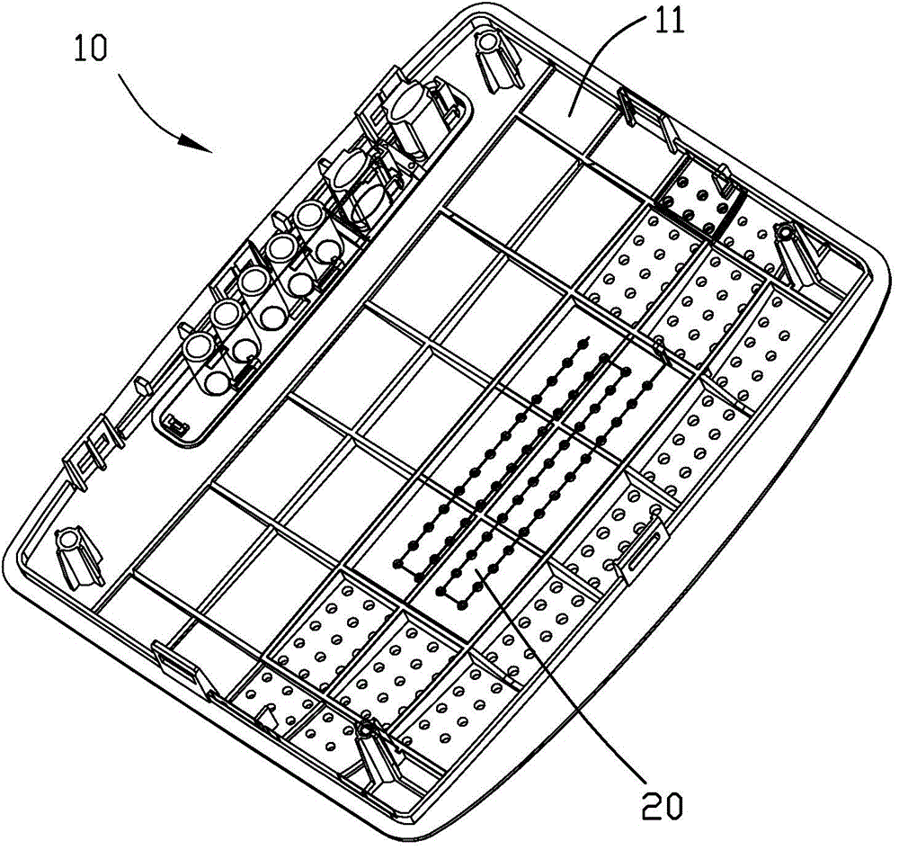
[0031] see figure 1 , the heat dissipation device 20 provided by the present invention is used to dissipate heat to the electronic device 10 , the electronic device 10 includes a casing 11 , and the heat dissipation device 20 is installed in the casing 11 .

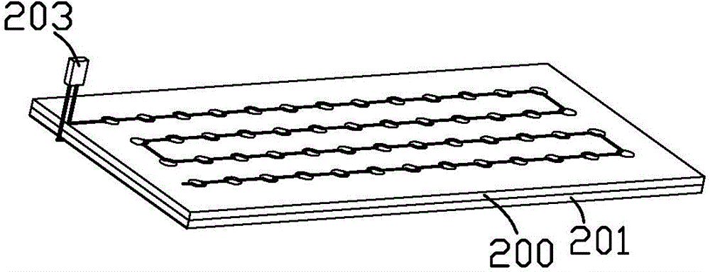
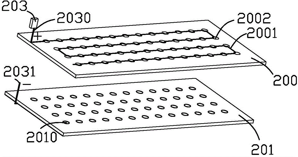
[0032] see figure 2 and image 3 , the heat dissipation device 20 is a flat plate structure as a whole, and the heat dissipation device 20 includes an insulating plate 200 , a conductive plate 201 and a power supply 203 . The power supply 203 includes a positive pole 2030 and a negative pole 2031. The positive pole 2030 is electrically connected to the circuit laid on the insulating plate 200, and the negative pole 2031 is electrically connected to the conductive plate 201. The power supply 203 provides piezoelectricity for the cooling device 20. In this embodiment, the voltage is High voltage electricity, high voltage electricity can be provided by common small transformers.

[0033] The insulating plate 200 is bonde...


PUM


Abstract

The invention provides a heat radiating device which integrally has a planar structure. The heat radiating device comprises an insulating board, a conductive board and a power supply. The power supply is connected with an external power supply for supplying high voltage to the heat radiating device. The insulating board comprises a metal filament. The power supply comprises an anode and a cathode. The anode is connected with the metal filament of the insulating board. The cathode is connected with the conductive board. The insulating board abuts against the conductive board. After the power supply supplies electric power to the heat radiating device, the metal filament ionizes adjacent air molecules for forming carbonium ions. The conductive board attracts the carbonium ions. A large amount of carbonium ions quickly move to the conductive board with negative electrons, and forced convection of air is formed, thereby realizing heat radiation.

Description

technical field [0001] The invention relates to a heat dissipation device, in particular to a heat dissipation device which generates forced convection of air to enhance the heat dissipation effect. Background technique [0002] Most of the 3C or consumer electronics products on the market today are designed towards the trend of thinner and lighter, and more and more functions are added in the limited space, which leads to higher and higher chip power consumption. As a result, a large amount of heat energy remains inside the product and cannot be discharged, which reduces the performance and life of the components. [0003] The solution to the lack of heat dissipation in general thin and light electronic products is nothing more than adding heat sinks, heat-conducting adhesives and other heat-dissipating components. However, due to space constraints, fans cannot be added. They all use natural convection to dissipate heat, and forced convection cannot be used to take heat out...

Claims


Application Information

Patent Timeline
IPC IPC(8): H05K7/20
Inventor 邱显桓
Owner 嘉兴匠欣印刷科技有限公司
Why Eureka
Try Eureka