Fuel cell system

A fuel cell system and fuel cell technology, applied in the direction of fuel cells, fuel cell additives, fuel cell recycling, etc., can solve the problems of cost-intensive, perfluorinated membrane consumption, etc., to achieve increased structural volume, rapid cooling Effects on start performance or cold start performance

Inactive Publication Date: 2015-09-23
BAYERISCHE MOTOREN WERKE AG
View PDF5 Cites 5 Cited by
  • Summary
  • Abstract
  • Description
  • Claims
  • Application Information

AI Technical Summary

Problems solved by technology

The perfluorinated membranes used are also complex and cost-intensive to produce

Method used


Image

  • Fuel cell system
  • Fuel cell system
  • Fuel cell system

Examples


Embodiment Construction

[0024] Only the components of the fuel cell system that are relevant here are shown in the figures, all other elements have been omitted for the sake of clarity.

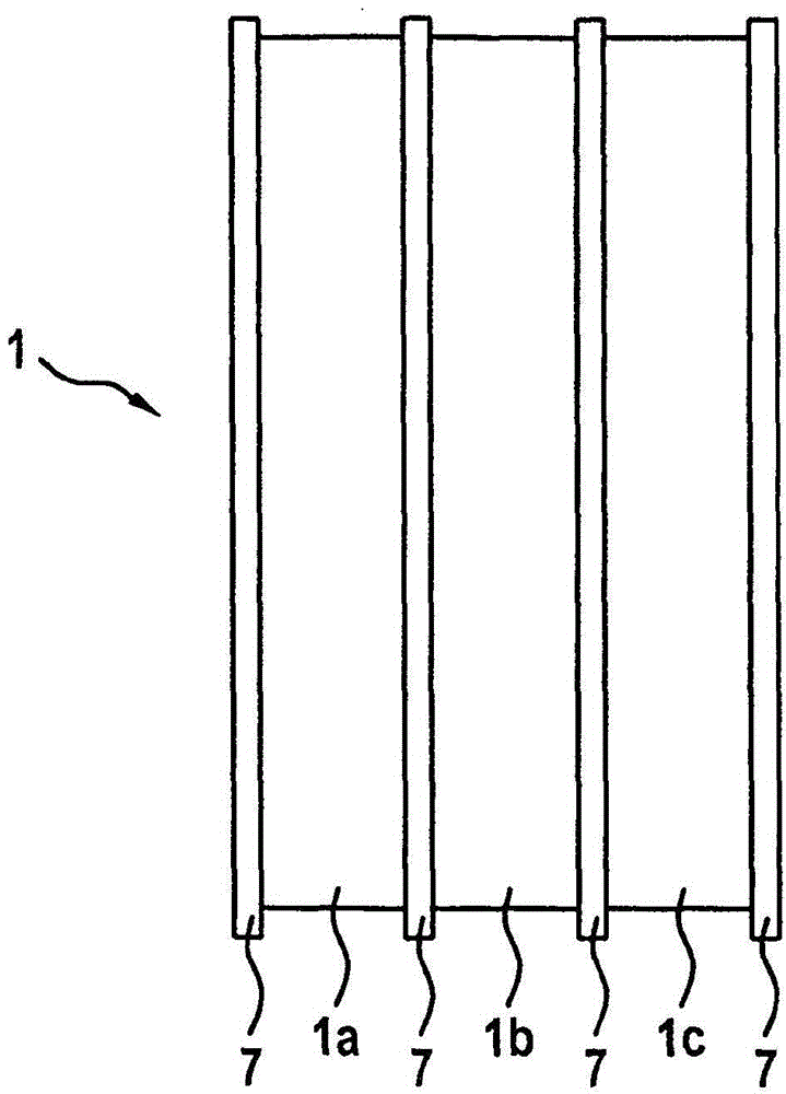
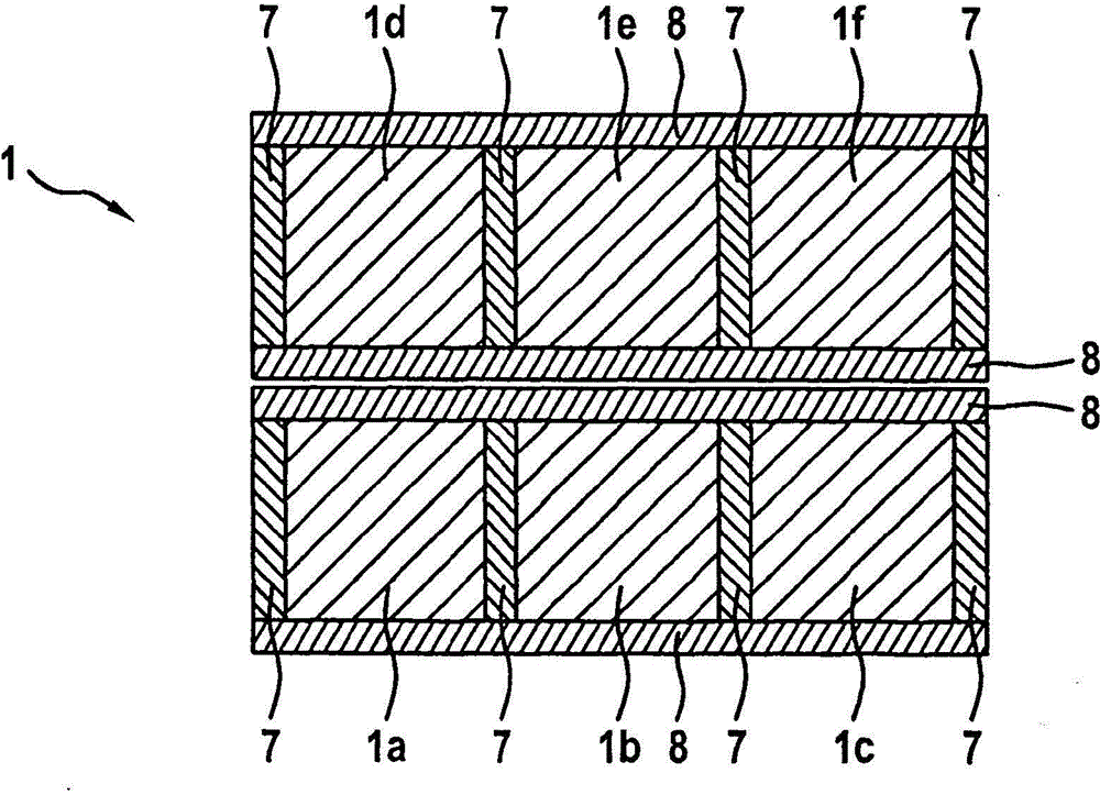
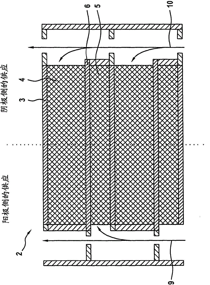
[0025] Figures 1 to 3 A fuel cell system 1 according to the invention is shown which has a plurality of substantially rectangular or square individual fuel cells 2 each organized into a stack 1a-1f. The individual fuel cells 2 each comprise an essentially planar membrane electrode unit 3, two gas diffusion layers 4, 5 in the form of fibers adjoining the opposite larger surfaces of the membrane electrode unit 3, and a bipolar plate 6. The bipolar plate establishes an electrical connection with the adjacent single fuel cell 2 located above or below it, including the active area surrounded by the edge area.

[0026] The bipolar plate 6 is completely planar in the active region, so that only the gas-conducting region is formed by the gas diffusion layers 4 , 5 , which accounts for at least 60% of the height of the ind...


PUM


Abstract

The present invention relates to a fuel cell system having a plurality of individual fuel cells which are combined to a stack, each of said individual fuel cells consisting of a substantially planar membrane-electrode unit, two gas diffusion layers in the form of a fiber structure and of a bipolar plate, which establishes the electrical connection to the adjacent individual fuel cell that is located above or below, wherein the gas diffusion layers adjoin the larger surfaces of the membrane electrode unit, which are located opposite of one another. The bipolar plate according to the invention comprises an active region surrounded by an edge region. In order to create a fuel cell system of the above-mentioned type, which is particularly thin, has no disadvantages in terms of weight, volume and power and moreover can be achieved in a cost-effective manner, it is proposed according to the invention that the bipolar plates in the active region have a completely flat design so that the gas-carrying region is formed exclusively by the gas diffusion layers, what amounts to at least 60% of the height of an individual fuel cell.

Description

technical field [0001] The invention relates to a fuel cell system with a plurality of individual fuel cells arranged in a stack, each comprising a substantially planar membrane electrode unit, two relatively large surfaces of the membrane electrode unit which are opposite each other The adjoining gas diffusion layer in the form of a fibrous structure and a bipolar plate, which establishes an electrical connection to the adjacent individual fuel cells located above or below it, includes an active area surrounded by an edge area. Background technique [0002] The fuel cell system achieves high power density by using a catalyst composed of platinum or an alloy containing platinum, among which, the application of 200 ~ 350cm 2 effective area. The fuel cell system usually has cooling plates in which a cooling medium is conducted. In order to generate a flow field for the cooling medium, shaped bipolar plates are usually required. Cost-intensive perfluorinated membranes are us...

Claims


Application Information

Patent Timeline
Patent Type & Authority Applications(China)
IPC IPC(8): H01M8/10H01M4/86H01M4/88H01M8/02H01M8/04
CPCY02E60/50Y02W30/86H01M8/241H01M8/008H01M8/0267H01M8/1002H01M8/04029H01M4/8605Y02E60/521H01M8/2418H01M8/1007Y02W30/84H01M8/0258H01M8/0247H01M8/04074H01M8/1004
Inventor S·哈斯J·施密德
Owner BAYERISCHE MOTOREN WERKE AG
Why Eureka
Try Eureka