CT system

A technology of tomographic imaging and cooling system, applied in computer tomography scanner, diagnosis, echo tomography, etc., can solve the problems of high noise level and achieve the effect of reducing noise level

Active Publication Date: 2015-09-30
SIEMENS HEALTHCARE GMBH
View PDF6 Cites 6 Cited by
  • Summary
  • Abstract
  • Description
  • Claims
  • Application Information

AI Technical Summary

Problems solved by technology

However, this also results in a higher noise level

Method used


Image

  • CT system
  • CT system
  • CT system

Examples


Embodiment Construction

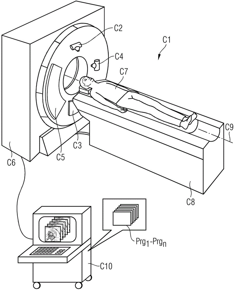
[0035] figure 1 An exemplary CT system C1 is shown. The CT system C1 comprises a gantry housing C6, in which there is a gantry (not shown here in detail) with a rotatable support, on which a first X-ray tube C2 and an opposite first detector device C3. Optionally, a second X-ray tube C4 and an opposite second detector C5 are provided. In addition, the CT system C1 also has a cooling system for removing waste heat from the electronic components from the rack housing C6, see Figure 2 to Figure 7 .

[0036] The patient C7 is on a patient couch C8 movable in the direction of the system axis C9, with which the patient can be moved continuously or sequentially along the system axis C9 during scanning with X-ray radiation through the X-ray tubes C2 and C4 and corresponding to the measurement field between detectors C3 and C5, respectively. Via the calculation and control unit C10 with the aid of the computer program Prg 1 to Prg n Control the process.

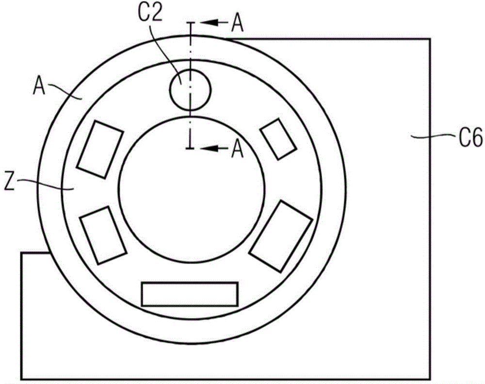
[0037] figure 2 A s...


PUM


Abstract

A CT system is disclosed for generating tomographic recordings of an examination object. In an embodiment, the CT system includes at least a gantry with a rotatable support for receiving components of the CT system, and a cooling system for cooling the components secured to the gantry with at least one air duct. In at least one embodiment, an incoming-air duct of the cooling system is divided into at least two segments to ensure uniform pressure distribution in the incoming-air duct.

Description

technical field [0001] The invention relates to a CT system for producing tomographic recordings of an object under examination, comprising at least: a gantry with a rotatable support for accommodating components of the CT system; and a cooling system for utilizing at least one ventilation The tubes cool the components fixed to the frame. Background technique [0002] The system components arranged on the rack of the CT system generate between 12 kW and 17 kW of heat during operation. For example in the case of generating X-ray radiation, most of the energy used in the X-ray tube of a CT system is converted into heat. To protect the system components, especially the radiator-detector system, this heat must be removed from the rack. To this end, it is necessary to supply the system components on the rotating support with sufficient cooling gas at all times. [0003] It is known to cool the individual components with additional fans mounted on a rotating support. However, ...

Claims


Application Information

Patent Timeline
Patent Type & Authority Applications(China)
IPC IPC(8): A61B6/03
CPCA61B6/4488A61B6/035A61B6/44A61B2560/04A61B2560/0406F28F9/026F28F9/0263F28F9/0265F28F9/0282H01L23/467H05G1/02H05G1/025
Inventor U.库恩C.威尔明
Owner SIEMENS HEALTHCARE GMBH
Why Eureka
Try Eureka