Check patentability & draft patents in minutes with Patsnap Eureka AI!

Strip-shaped float valve

A float valve and strip technology, which is applied in the chemical method, distillation separation, and dispersion separation of liquid and gas medium, etc., can solve the problems of reduced tray efficiency, increased liquid foam entrainment, easy to fall off, etc. The effect of increasing the gas-liquid contact area, increasing the mass transfer efficiency and prolonging the service life

Inactive Publication Date: 2015-09-30
SUZHOU KD PETROCHEM ENG
View PDF8 Cites 0 Cited by
  • Summary
  • Abstract
  • Description
  • Claims
  • Application Information

AI Technical Summary

Problems solved by technology

[0004]F1 type (also known as V1 type) valve tray is the most commonly used tray, but production practice shows that the F1 type float valve has the following problems during use : (1) Due to the different liquid levels on the tray, when the float valves are blown up, the time and degree of each float valve being blown open are inconsistent; (2) The air flow is blown into the liquid from around the valve hole. layer, no orientation, increased entrainment of liquid foam, and reduced tray efficiency; (3) The large bubbles bulging from the valve hole cannot effectively break them up and refine them, so that the gas-liquid contact mass transfer area is small, affecting mass transfer Efficiency improvement; (4) Float valve is seriously worn and easy to fall off

Method used


Image

  • Strip-shaped float valve
  • Strip-shaped float valve
  • Strip-shaped float valve

Examples


Embodiment 1

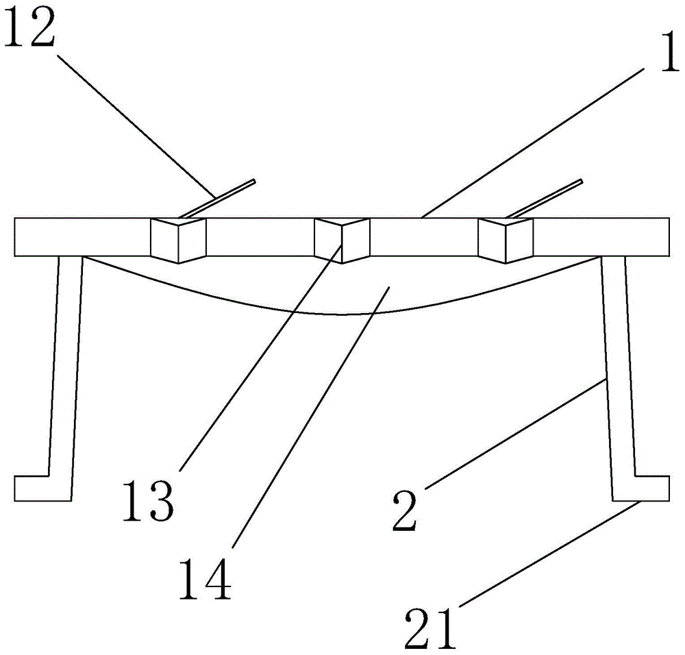
[0021] Such as figure 1 , figure 2 and image 3 The strip float valve of this embodiment shown includes a rectangular bonnet 1 and two valve legs 2. The bottom of the bonnet 1 is provided with a middle height and low protrusions 14 around. The ratio of the long side to the short side of the bonnet 1 is The ratio is 2:1. There are two tongue holes 11 on the valve cover 1. The top of the valve cover 1 is provided with an inclined baffle 12 at the tongue hole 11. The angle between the baffle 12 and the valve cover 1 is 20° to 30°. , the two long sides of the valve cover 1 are provided with teeth 13 bent towards the bottom of the valve cover 1, the valve legs 2 are arranged at the bottom of the valve cover 1 close to the two short sides, and the two valve legs 2 are respectively inclined to the outside, The angle between the valve leg 2 and the valve cover 1 is 75° to 80°. The valve leg 2 is made of elastic metal material. The lower end of the valve leg 2 is provided with a va...

Embodiment 2

[0023] The remaining technical features of the strip float valve in this embodiment are the same as in Embodiment 1, except that the angle between the baffle plate 12 and the valve cover 1 is 30°, and the angle between the valve leg 2 and the valve cover 1 is 80°. .

Embodiment 3

[0025] The rest of the technical features of the strip float valve in this embodiment are the same as those in Embodiment 1, except that there are three tongue holes, the included angle between the baffle plate 12 and the valve cover 1 is 25°, and the valve leg 2 and the valve cover The angle between 1 is 80°.


PUM


Abstract

The invention relates to a float valve and belongs to the technical field of chemical equipment for gas-liquid mass transfer separation in the chemical industry. The float valve comprises a quadrangular valve cover and two valve legs and is characterized in that an embossment high in the middle and low in the periphery is formed in the bottom of the valve cover; at least one tongue hole is formed in the valve cover, and an obliquely arranged baffle is arranged at the tongue hole of the top of the valve cove; teeth are arranged on two opposite sides of the valve cover; the valve legs are arranged at the bottom of the valve cover, close to the other two sides; the valve legs are inclined outwards respectively and are made of elastic metal materials; a valve foot is arranged at the lower end of each valve leg; a corrosion resistant coating coats the outer surface of the float valve. According to the float valve, the vibration during use can be effectively reduced and the service life of the float valve can be prolonged.

Description

technical field [0001] The invention relates to a float valve, belonging to the technical field of chemical equipment for gas-liquid mass transfer separation in the chemical industry. Background technique [0002] Tray tower is a kind of graded contact mass transfer equipment used in gas-liquid or liquid-liquid system. It consists of a cylindrical tower body and a number of trays installed horizontally in the tower at a certain distance. It is widely used in rectification and absorption, and can also be used as a reactor for gas-liquid phase reaction process. During operation, the liquid flows through each layer of trays from top to bottom under the action of gravity, and is discharged from the bottom of the tower; the gas is driven by the pressure difference, and passes through each layer of trays from bottom to top, and is discharged to the top of the tower. A certain depth of liquid layer is maintained on each tray, and the gas is dispersed into the liquid layer through ...

Claims


Application Information

Patent Timeline
IPC IPC(8): B01D3/20B01D53/18B01J10/00
Inventor 孔逸君徐耀刚孙涛叶丽萍牛录元
Owner SUZHOU KD PETROCHEM ENG
Features
  • R&D
  • Intellectual Property
  • Life Sciences
  • Materials
  • Tech Scout
  • Unparalleled Data Quality
  • Higher Quality Content
  • 60% Fewer Hallucinations
Learn More