
Grain cutting machine

A granulator and granulation technology, which is applied in the direction of coating, etc., can solve the problems of easy wear of the knife edge of the granulator, fast aging speed of the rubber roller, and easy rust, etc., and achieve the goals of slowing down the speed of corrosion, long service life, and slowing down wear. Effect

Inactive Publication Date: 2015-09-30
WUHU XINNING NEW MATERIAL SCI & TECH CO LTD
View PDF5 Cites 5 Cited by
  • Summary
  • Abstract
  • Description
  • Claims
  • Application Information

AI Technical Summary

Problems solved by technology

[0003] The purpose of the present invention is to provide a granulator, which overcomes the problems of easy corrosion of general equipment, easy wear of the knife edge of the granulator and fast aging of rubber rollers, and effectively prolongs the service life of the granulator

Method used


Image

  • Grain cutting machine

Examples


Embodiment Construction

[0021] Specific embodiments of the present invention will be described in detail below in conjunction with the accompanying drawings. It should be understood that the specific embodiments described here are only used to illustrate and explain the present invention, and are not intended to limit the present invention.

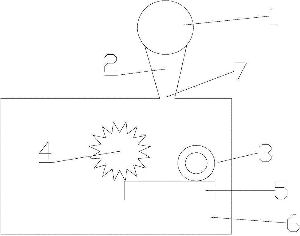
[0022] like figure 1 The present invention as shown provides a kind of granulator, and this granulator comprises: tooling mechanism, cooling fan 1, air inlet channel and granulator body 6, and described tooling mechanism is arranged in described granulator body 6, The pelletizer body 6 is provided with an air inlet 7, and the air inlet 7 is connected to one end of the air inlet 2, and the other end of the air inlet 2 is connected to the cooling fan 1, and the air inlet 7 is connected to one end of the air inlet 2. The wind direction of the air inlet channel 2 blowing into the pelletizer body 6 corresponds to the tooling mechanism.

[0023] Through the above-me...


PUM


Abstract

The invention discloses a grain cutting machine. The grain cutting machine comprises a tooling mechanism, a cooling draught fan (1), an air inlet duct (2) and a grain cutting machine body (6). The tooling mechanism is arranged in the grain cutting machine body (6). An air inlet (7) is formed in the grain cutting machine body (6). The air inlet (7) is communicated with one end of the air inlet duct (2). The other end of the air inlet duct (2) is communicated with the cooling draught fan (1). The wind direction flowing into the grain cutting machine body (6) of the air inlet duct (2) corresponds to the tooling mechanism. The grain cutting machine solves the problems that a knife edge of the grain cutting machine is prone to wear, and the aging speed of a rubber roll is high, and the service life of the grain cutting machine is prolonged effectively.

Description

technical field [0001] The invention relates to the field of extrusion production of granular raw materials, in particular to a pelletizer. Background technique [0002] In the process of plastic extrusion production, the plastic raw material is melted and extruded through the extruder at high temperature. When the plastic melt comes out of the die of the extruder, it appears as a line. The molten plastic becomes a line after being cooled by the water tank. At this time, the plastic has solidified from a molten state to a solid state, but it still has a high temperature of tens of degrees, and there are a lot of water stains on the surface. These strand-shaped plastics enter the pelletizer, which cuts them into particles with a length of tens of millimeters. Due to the high extrusion speed, the cooling time of the linear plastic in the water tank is very short, and most of its own high temperature is transferred to the pelletizing motor knife, pelletizing machine fixed knif...

Claims


Application Information

Patent Timeline
IPC IPC(8): B29B9/06B29B9/16B29B13/04B29B13/06
CPCB29B9/06B29B9/16B29B13/045B29B13/065
Inventor 罗会鹏
Owner WUHU XINNING NEW MATERIAL SCI & TECH CO LTD
Learn More