Central rotating equipment support

A technology for rotating equipment and supports, applied in mechanical equipment, non-rotating vibration suppression, supporting machines, etc., can solve problems such as increasing motor power, wasting electric energy, increasing friction between fixed supports and rotating central axis, and reducing screw The rate of corrosion, the reduction of the possibility of screw rusting, the effect of smooth rotation

Inactive Publication Date: 2019-09-13
艾德维斯智能科技(苏州)有限公司
View PDF1 Cites 0 Cited by
  • Summary
  • Abstract
  • Description
  • Claims
  • Application Information

AI Technical Summary

Problems solved by technology

[0002] Traditional center-rotating water treatment mixers and mud scrapers and other equipment all use fixed supports. The traditional supports produce a binding force on the rotating central axis in the opposite direction of rotation, increasing the output torque of the drive motor, increasing the power of the motor, and wasting Electric energy, and increase the friction between the fixed support and the rotating central shaft, resulting in serious wear and tear of the fixed support, which needs to be replaced frequently, and even leads to loosening of the fixed parts. Therefore, people began to study supports that can reduce wear and friction. With the emergence of various bearings, it was found that the bearings can effectively reduce the friction and wear of the central shaft, so the bearings are also used on the support
[0003] Chinese patent has announced a kind of central axis rotating equipment support (publication number is CN204051582U), this central axis rotating equipment support, structure is stable and reliable, maintenance cost is low, operating power consumption can reduce about 50%, but in the actual use process Most of the screws and other connecting parts of the support are directly exposed to the outside. When water seepage or water leakage occurs, the water will penetrate into the gap between the bolts and the flange, which will accelerate the corrosion rate of the bolts and make it difficult to disassemble the bolts. The disassembly and maintenance of the support is more difficult, therefore, those skilled in the art provide a central rotating equipment support to solve the problems raised in the above-mentioned background technology

Method used


Image

  • Central rotating equipment support
  • Central rotating equipment support
  • Central rotating equipment support

Examples


Embodiment 1

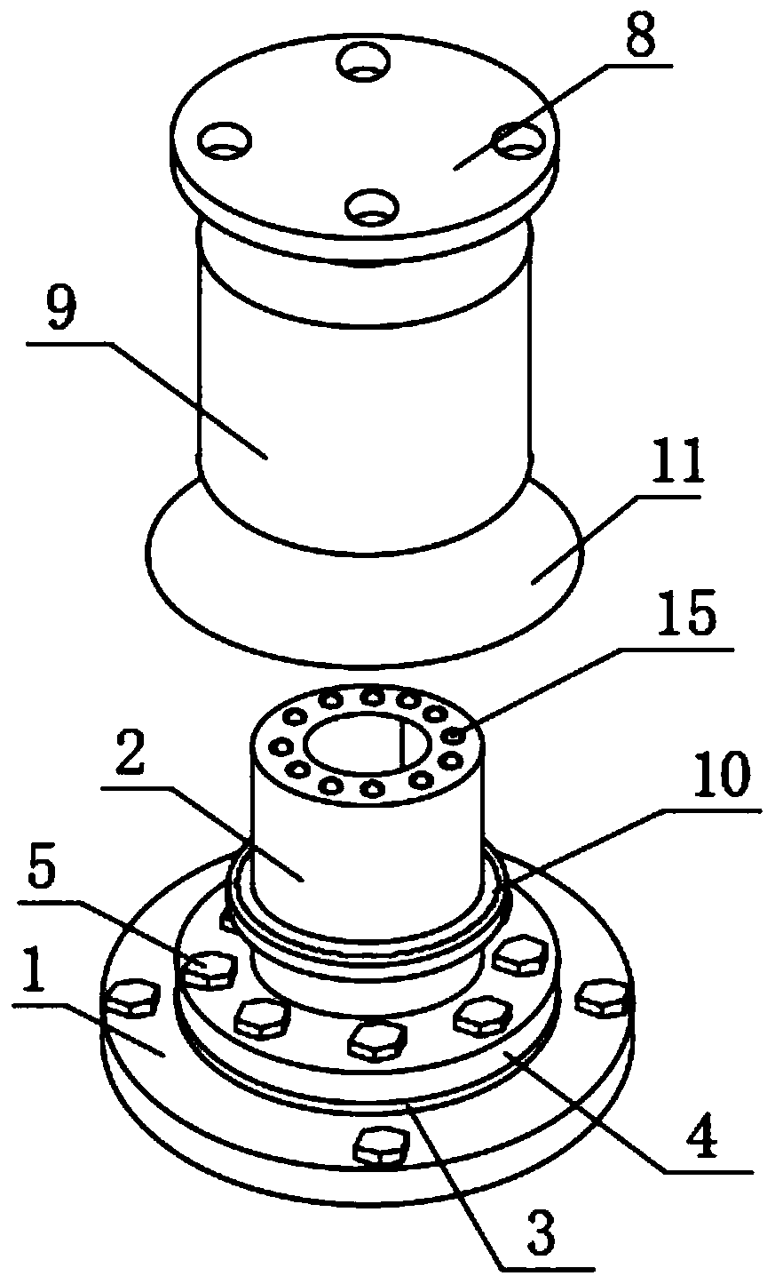
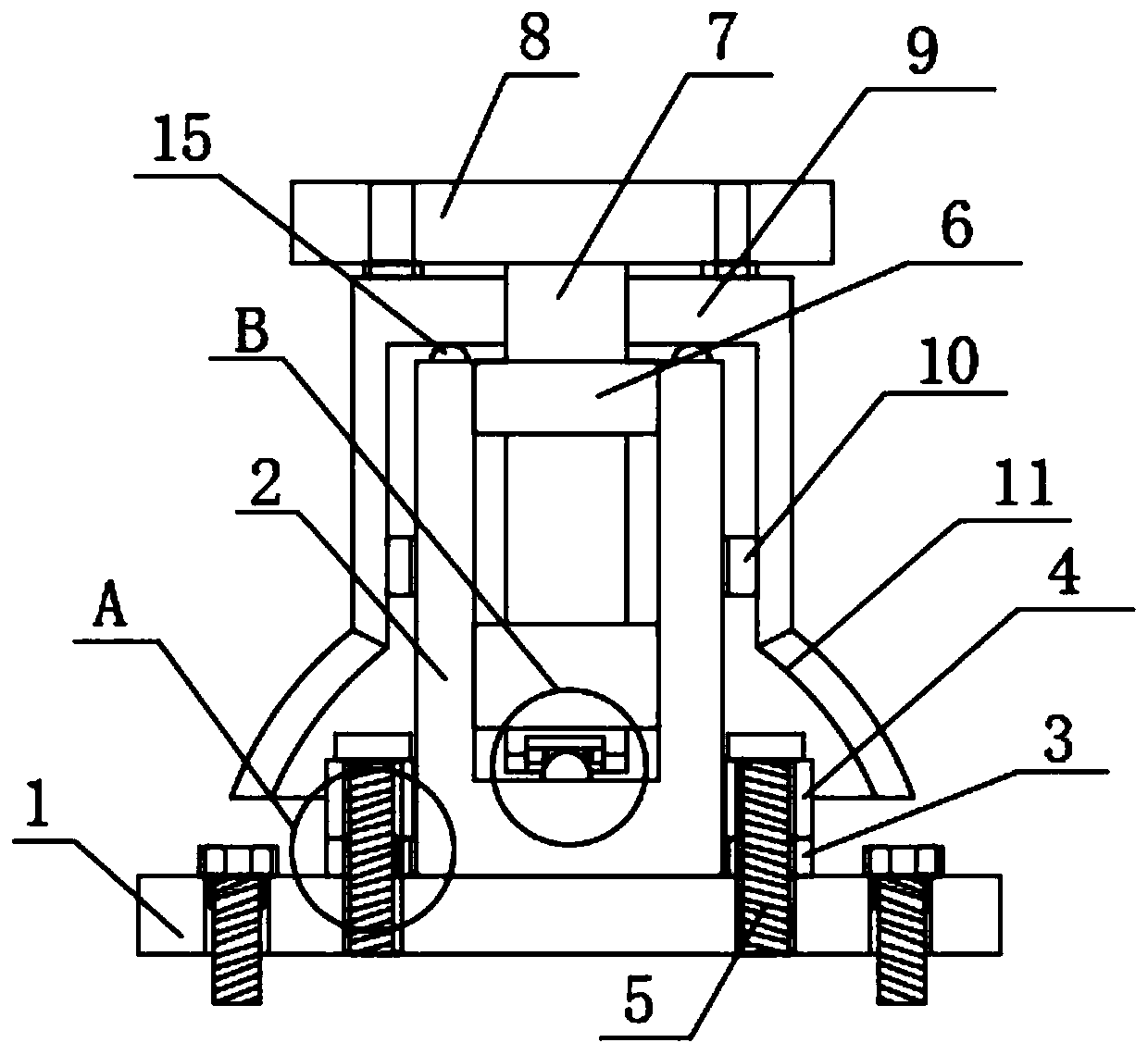
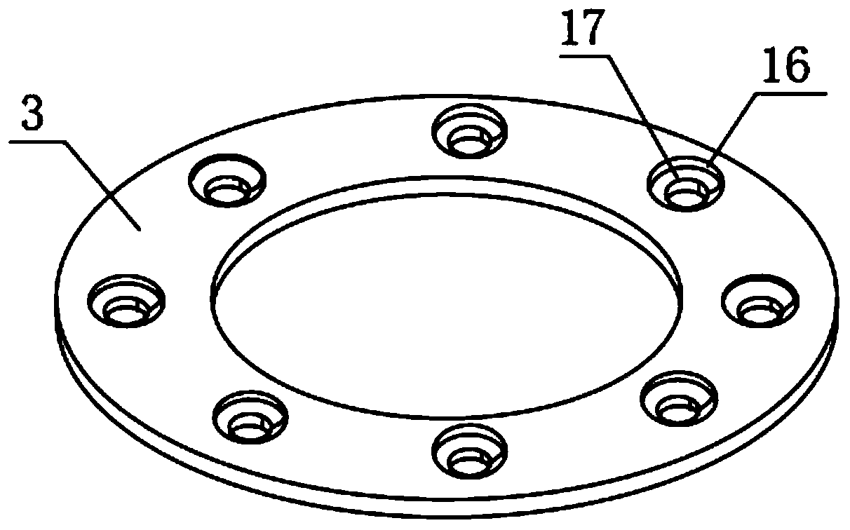
[0021] see Figure 1~5 , in an embodiment of the present invention, a central rotating equipment support includes a base 1, a sleeve 2 is fixedly connected to the top of the base 1, the surface of the sleeve 2 is sleeved with a rubber pad 3, and the surface of the sleeve 2 is sleeved with The flange 4 located above the rubber pad 3, the top of the rubber pad 3 is provided with a water blocking hole 16, the top of the flange 4 is threaded with a screw 5, the screw 5 penetrates the water blocking hole 16 and is threaded with the base 1, the water blocking hole The middle part of the inner wall of 16 is provided with a protruding block 17, and the protruding block 17 makes the screw 5 interfere with the water blocking hole 16. The inner wall of the base 1 is fixedly connected with two first bearings 6, and the inner wall of the first bearing 6 A rotating shaft 7 is sleeved on the edge of the rotating shaft 7, and the top of the rotating shaft 7 is fixedly connected with a rotatin...

Embodiment 2

[0024] see Figure 1~5 , on the basis of Embodiment 1, a further improvement is made: the bottom of the inner wall of the sleeve 2 is provided with a steel ball 12, the bottom of the rotating shaft 7 is provided with a hollow groove 13, and the inner wall of the hollow groove 13 is fixedly connected with a third bearing 14, the third The diameter of the inner edge of the bearing 14 is smaller than the diameter of the steel ball 12, and the third bearing 14 is sleeved on the surface of the steel ball 12, which can play a good supporting effect on the rotating shaft 7 without affecting the rotation of the rotating shaft 7, and avoid the rotating shaft 7 being damaged. The pressure is all applied on the first bearing 6 and the second bearing 10, which reduces the burden on the first bearing 6 and the second bearing 10, and makes the support more stable in use.

[0025] Wherein, the top of the casing 9 is fixedly connected with a rubber ring, and the top of the rubber ring is prov...


PUM


Abstract

The invention relates to the technical field of water treatment equipment, in particular to a central rotating equipment support. The central rotating equipment support comprises a base, wherein the top of the base is fixedly connected with a sleeve, the surface of the sleeve is sleeved with a rubber pad, the surface of the sleeve is sleeved with a flange positioned above the rubber pad, the top of the rubber pad is provided with a water blocking hole, the top of the flange is in screwed connection with a screw, the screw penetrates through the water blocking hole and is in screwed connectionwith the base, the inner wall of the base is fixedly connected with two first bearings, the inner edges of the first bearings sleeve a rotating shaft, and the top of the rotating shaft is fixedly connected with a rotating disc. The equipment solves the problems that most connecting pieces such as screws of the support are directly exposed to the outside, when water seepage or water leakage occurs,water can permeate into the gap between a bolt and the flange, the corrosion rate of the bolt is accelerated, the bolt is likely to be difficult to disassemble, and disassembly and maintenance of thesupport are more difficult.

Description

technical field [0001] The invention relates to the technical field of water treatment equipment, in particular to a central rotating equipment support. Background technique [0002] Traditional center-rotating water treatment mixers and mud scrapers and other equipment all use fixed supports. The traditional supports produce a binding force on the rotating central axis in the opposite direction of rotation, increasing the output torque of the drive motor, increasing the power of the motor, and wasting Electric energy, and increase the friction between the fixed support and the rotating central shaft, resulting in serious wear and tear of the fixed support, which needs to be replaced frequently, and even leads to loosening of the fixed parts. Therefore, people began to study supports that can reduce wear and friction. With the emergence of various bearings, it was found that the bearings can effectively reduce the friction and wear of the central shaft, so the bearings are a...

Claims


Application Information

Patent Timeline
IPC IPC(8): F16M11/08F16M11/22F16F15/08F16B41/00F16B33/00B01D21/18B01F15/00
CPCF16M11/08F16M11/22F16M11/2014F16F15/08F16B41/00F16B33/008F16B33/004B01D21/18B01F35/31B01F2101/305
Inventor 刘凯
Owner 艾德维斯智能科技(苏州)有限公司
Why Eureka
Try Eureka