Remote Monitoring of Pipelines using Wireless Sensor Network

a wireless sensor and remote monitoring technology, applied in the direction of hydrodynamic testing, fluid tightness measurement, instruments, etc., can solve the problems of unanticipated failure, high cost, and current use of considerable expense and effort in the energy and chemical processing sectors, and achieve low cost, low cost, and low cost

Inactive Publication Date: 2005-07-07
SOUTHWEST RES INST
View PDF4 Cites 162 Cited by
  • Summary
  • Abstract
  • Description
  • Claims
  • Application Information

AI Technical Summary

Benefits of technology

[0010] An embodiment of the present invention provides a method and system for in-situ inspection of pipelines with a low power wireless sensor network that are small, low cost, and rugged. The system includes a device for introducing electromagnetic radiation into the pipeline such that the pipe acts as a wave-guide for the electromagnetic radiation. The system includes a network of nodes to transmit a

Problems solved by technology

Considerable expense and effort is currently employed in the energy and chemical processing sectors to conduct necessary inspections of pipelines and other piping systems (e.g., cooling water and process stream piping).
Often, these inspections require system shut down and in some cases excavation resulting in the high expenses encountered.
Depending on the size of the interval, however, significant degradation can occur between inspections that can in turn result in unanticipated failures.
A key problem with using pigs is that around 30% of natural gas transmission pipelines in United States are not piggable due to various constraints such as sharp bends, diameter changes, and valving systems.
According to the US Department of Transportation Office of Pipeline Safety (OPS), internal corrosion caused about 15 percent of all gas transmission pipeline repor

Method used


Image

  • Remote Monitoring of Pipelines using Wireless Sensor Network
  • Remote Monitoring of Pipelines using Wireless Sensor Network
  • Remote Monitoring of Pipelines using Wireless Sensor Network

Examples


Embodiment Construction

[0017] While the present invention will be described more fully it is to be understood at the outset of the description which follows that persons of skill in the appropriate arts may modify the invention herein described while still achieving the favorable results of this invention. Accordingly, the description which follows is to be understood as being a broad, teaching disclosure directed to persons of skill in the appropriate arts, and not as limiting upon the present invention.

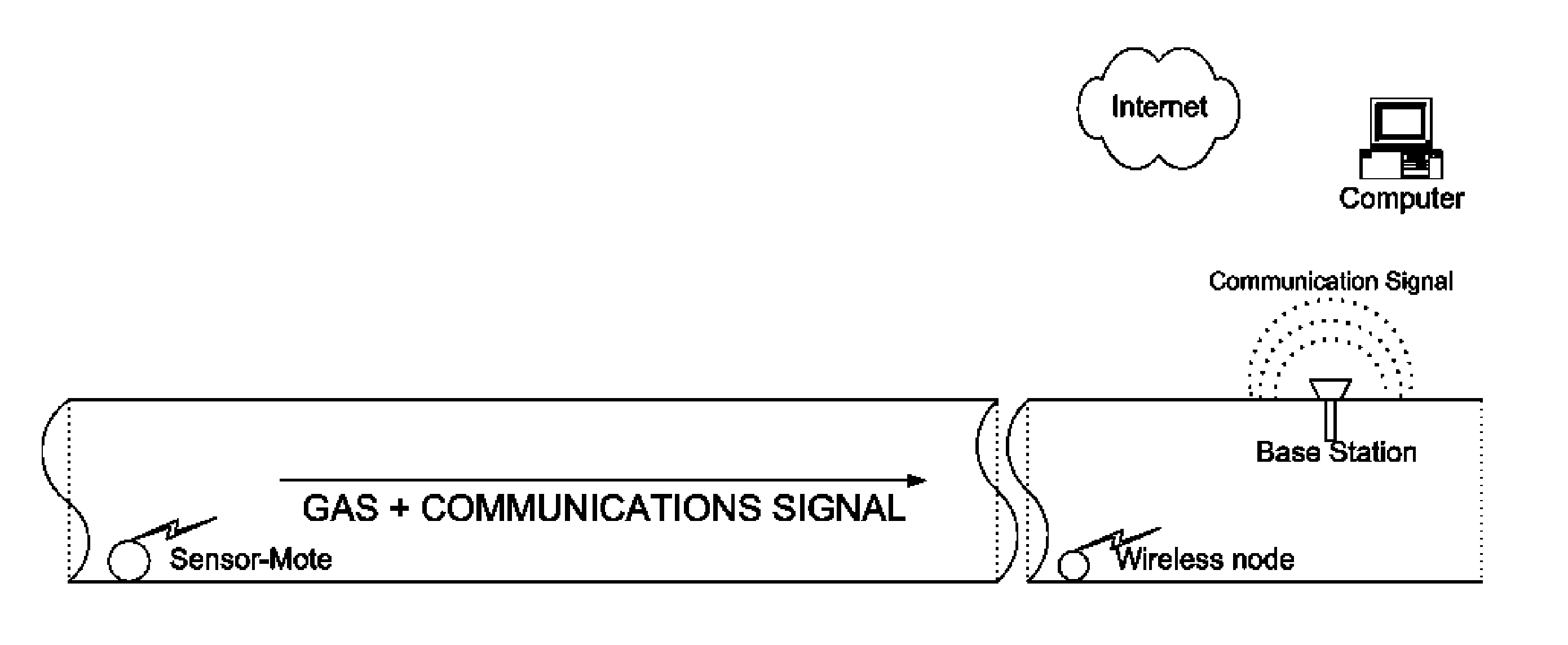
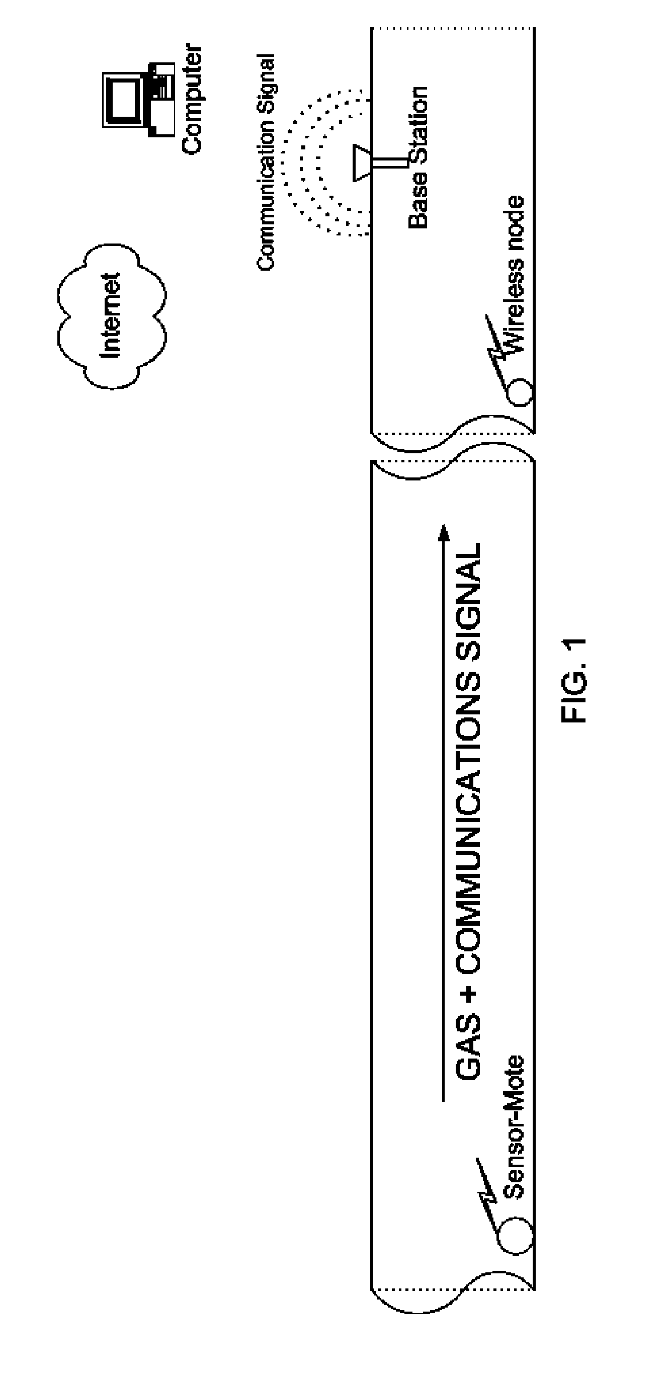
[0018] First briefly in overview, the present invention involves the establishing of a sensor network in existing gas pipelines (both transmission and distribution) and new pipelines, then collecting the sensor data from multiple sites for input into a recommendation engine that provides maintenance alerts for repair of the pipeline. The system may be more easily understood by its use in gas pipelines with the understanding that the foregoing is also broadly applicable in other domains. There are some 80...


PUM


Abstract

A wireless sensor system is installed inside pipelines using sensors and wireless transceivers that are small, low-cost, and rugged. The objective is monitoring the pipeline and recommending maintenance and repair at specific locations in the pipeline. Maintenance includes detection of leaks and prevention of catastrophic failures as a result of internal corrosion or other damage, such as third party mechanical damage, using multitude of sensors. After establishing the wireless sensor network the network is activated so the sensor can make measurements periodically or continuously using instructions transmitted via the base station. The sensor data from the various sensors are transmitted inside the pipe and extracted to access points in the pipeline to a remote computer that stores the data within the computer memory. The sensed information can be used for monitoring as well as analysis using a recommendation engine to provide maintenance and repair alerts.

Description

REFERENCES CITED [0001] U.S. Patent Documents 5994984May 29, 1998Stancil et al.333 / 2486662099May 22, 2001Knaian et al.701 / 117 Other References [0002] D. Burwell, N. Sridhar, O. C. Moghissi, and L. Perry, Internal Corrosion Direct Assessment Of Dry Gas Transmission Pipelines—Validation, CORROSION / 2004 paper No. 04195, NACE International, Houston, Tex., (2004).STATEMENT REGARDING FEDERALLY SPONSORED RESEARCH AND DEVELOPMENT [0003] Portions of the research for the invention were done under a Department of Energy (DOE) grant number DE-FG02-04ER83895.BACKGROUND OF THE INVENTION [0004] Considerable expense and effort is currently employed in the energy and chemical processing sectors to conduct necessary inspections of pipelines and other piping systems (e.g., cooling water and process stream piping). Often, these inspections require system shut down and in some cases excavation resulting in the high expenses encountered. As a consequence, such inspections are conducted at periodic inter...

Claims


Application Information

Patent Timeline
IPC IPC(8): G01N17/00
CPCG01N17/00
Inventor SABATA, ASHOKBROSSIA, SEAN
Owner SOUTHWEST RES INST
Why Eureka
Try Eureka