
Low or non oxidizing heat accumulating type burner

A burner, non-oxidation technology, applied in burners, gas fuel burners, combustion methods, etc., can solve the problems of affecting the installation space of the furnace body, bulky shape, and low airflow ejection speed, so as to improve energy utilization. , The effect of improving the operating environment and increasing the injection speed

Inactive Publication Date: 2015-09-30
BEIJING JJRS TECH DEV +1
View PDF8 Cites 2 Cited by
  • Summary
  • Abstract
  • Description
  • Claims
  • Application Information

AI Technical Summary

Problems solved by technology

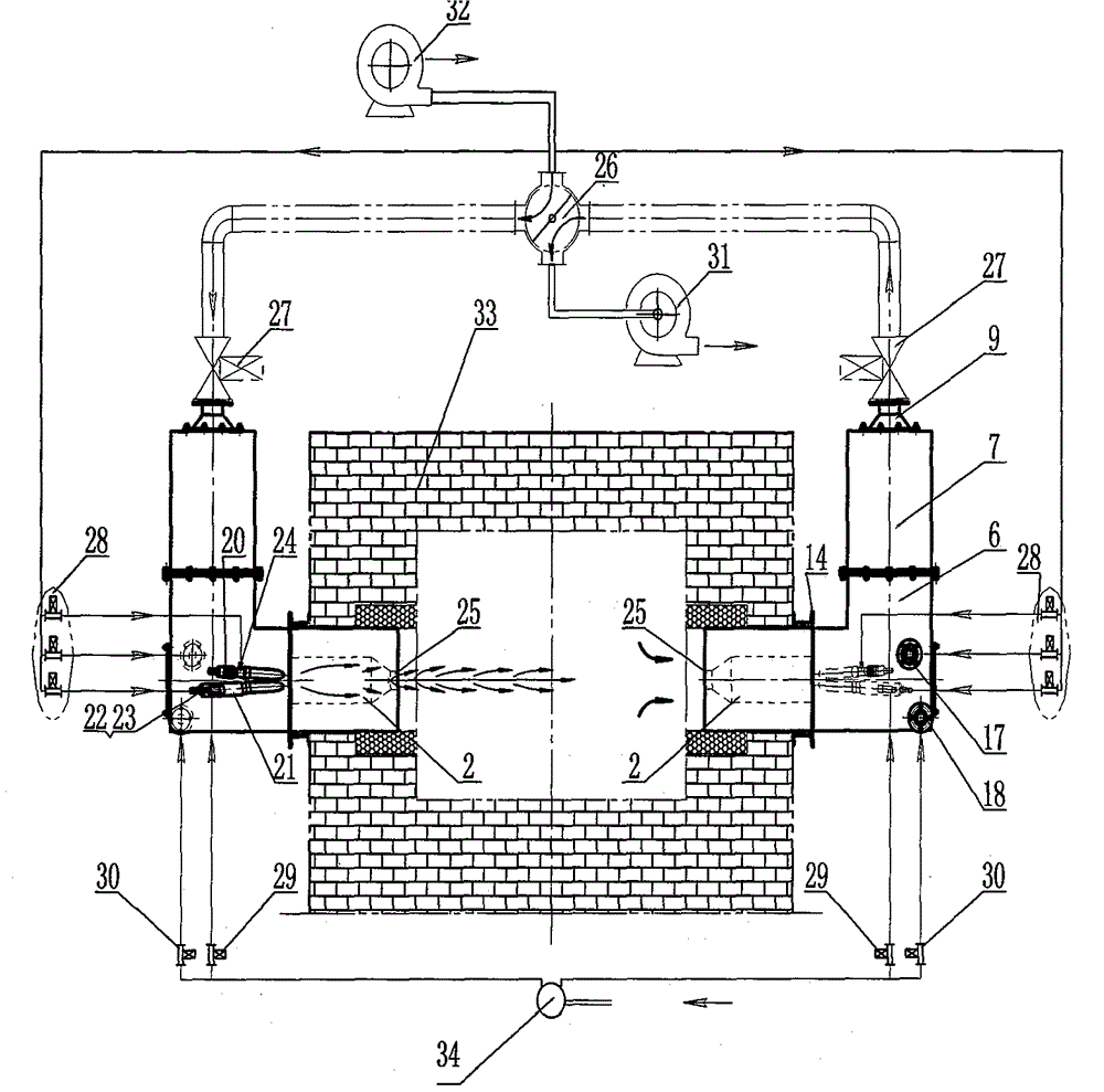
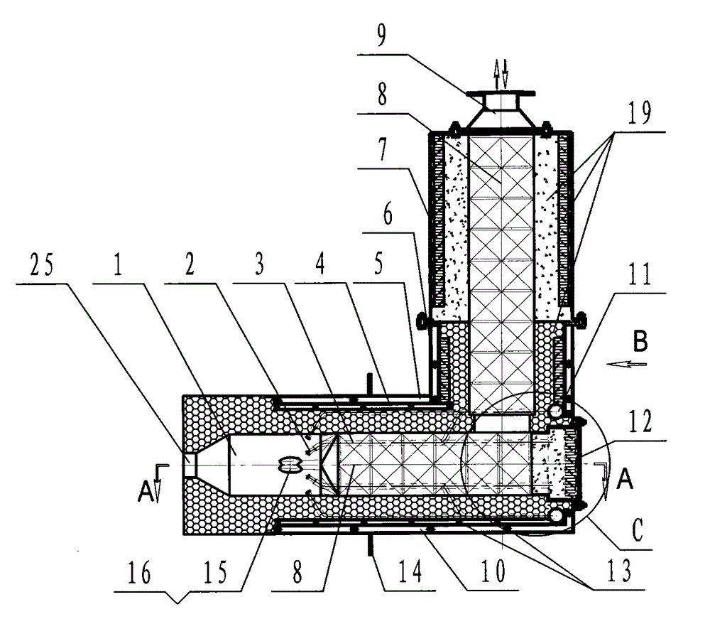
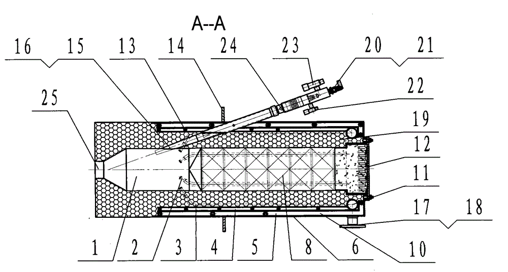
[0006] In order to overcome the gas and air in the above-mentioned prior art that are directly transported into the furnace for mixed combustion, part of the oxygen-containing air that appears is in direct contact with the metal parts in the furnace, causing the metal parts to be oxidized in the furnace, and the existing heat storage The air flow rate of the regenerative burner is low, and it is not easy to form the air circulation in the furnace, resulting in poor furnace temperature uniformity. In addition, in order to reduce the heat dissipation on the outer surface of the regenerative burner, its appearance is bulky, resulting in excessive consumption of raw materials for production, which affects the furnace temperature. In order to solve problems such as body installation space, the present invention provides a low-oxidation and non-oxidative regenerative burner, which includes a burner box, an air flue gas interface (9) is set at one end of the box body, and a flame gas nozzle (25) is set at the other end ), and a heat accumulator is set inside the box, and it is characterized in that a combustion chamber (1) is arranged near the flame nozzle (25) inside the burner box, and the combustion chamber (1) It communicates with the flame gas nozzle (25), and the supplementary combustion air, main gas and main air are introduced into the combustion chamber (1) to form a mixed

Method used


Image

  • Low or non oxidizing heat accumulating type burner
  • Low or non oxidizing heat accumulating type burner
  • Low or non oxidizing heat accumulating type burner

Examples


Embodiment Construction

[0033] In order to make the object, technical solution and advantages of the present invention more clear, the implementation of the present invention will be described in detail below in conjunction with specific embodiments and corresponding drawings. It is stated here that the exemplary embodiments and descriptions of the present invention are only used as explanations of the present invention, not as limitations of the present invention.

[0034] The low-oxidation and non-oxidative regenerative burner provided by the present invention is suitable for gas fuels, especially gas fuels with high calorific value such as liquefied gas and natural gas, and is mainly used for galvanizing furnaces, heat treatment furnaces, and steel rolling heating furnaces that require less and no oxidation to heat workpieces. , Forging furnaces and other industrial furnaces.

[0035] combine figure 1 , figure 2 , image 3 and Figure 4 As shown, the less non-oxidizing regenerative burner is ...


PUM


Abstract

The invention provides a low or non oxidizing heat accumulating type burner. The low or non oxidizing heat accumulating type burner comprises a burner box body, one end of the box body is provided with an air and smoke connector (9), the other end of the box body is provided with flame gas nozzles (25), and a heat accumulating body is arranged in the box body. The low or non oxidizing heat accumulating type burner is characterized in that a burning chamber (1) is arranged on a position, close to the flame gas nozzles (25), in the burner box body, the burning chamber (1) is communicated with the flame gas nozzles (25), afterburning air, main fuel gas and main air are pumped into the burning chamber (1) to be mixed, a multi-layer structure is adopted by a shell of the burner box body, heat exchange is carried out in shell cavities (10) by using the afterburning air or the main fuel gas, and meanwhile mixing cavity bodies (11) are arranged, so that mixing of the afterburning air and the main fuel gas is completed in the mixing cavity bodies (11). Recycling shell heat dissipation can be achieved, by means of premixing and internal burning structures, the spouting velocity of flames is improved, disturbance of furnace inside atmosphere is increased, and the uniformity of furnace temperature is improved.

Description

technical field [0001] The invention relates to a continuous heat treatment furnace for metal plates and strips, in particular to a regenerative burner which is heated by an open flame and installed in pairs to create a non-oxidizing atmosphere. Background technique [0002] At present, there are various forms of regenerative burners mainly developed at home and abroad, and their working characteristics and principles are similar. Regenerative burners should be installed on both sides of the furnace body in pairs or in groups. The burner burner burns, and the burner burner on the other side exhausts smoke. When working, the fuel, air and flue gas are reversed at the same time after a certain period of time, and the burner that burns on one side is reversed to smoke exhaust, and the burner that exhausts smoke on the other side is reversed to burn. Through continuous circulation of this process, the heat in the exhausted flue gas is absorbed by the regenerator installed in th...

Claims


Application Information

Patent Timeline
IPC IPC(8): F23D14/02F23D14/62F23D14/66F23D14/58F23D14/46C21D9/56C21D1/52
CPCC21D1/52C21D9/562F23D14/02F23D14/46F23D14/58F23D14/62F23D14/66F23D2203/007Y02E20/34
Inventor 章金法许雷
Owner BEIJING JJRS TECH DEV
Learn More