Air conditioning system, air conditioner, and control method for air conditioning system

An air-conditioning system and air-conditioner technology, which is applied in the control field of air-conditioning systems, air-conditioners, and air-conditioning systems, can solve problems such as excessive cost, energy waste, and low energy consumption, and achieve improved heating effects and user experience The effect of precision

Active Publication Date: 2015-09-30
GD MIDEA HEATING & VENTILATING EQUIP CO LTD +1
View PDF16 Cites 11 Cited by
  • Summary
  • Abstract
  • Description
  • Claims
  • Application Information

AI Technical Summary

Problems solved by technology

[0002] When the outdoor ambient temperature is too low or the outdoor air humidity is high, common household air conditioners or commercial large-scale central air conditioners may cause problems such as a drop in evaporation temperature of the air conditioning system, low heating efficiency, and frosting when heating. Most of the system uses reverse cycle defrosting, four-way valve reverse cycle defrosting will cause problems such as oil rush, system pressure difference change and system reliability reduction. At the same time, the outdoor ambient temperature and air humidity cannot be artificially changed and even if they are changed The outdoor environmental conditions also require too much cost, and it is impossible to achieve the non-frost operating characteristics of the air conditioning system
[0003] In addition, some household air conditioners or large commercial central air conditioners require less energy consumption for cooling or heating during the transition season, but the energy consumption of general household air conditioners or large commercial central air conditioners is less in the transition season. If there is no reduction, it is impossible to automatically adjust the circulation flow of the air conditioning system according to the indoor and outdoor ambient temperature and the load of the air conditioner, which leads to a waste of energy

Method used


Image

  • Air conditioning system, air conditioner, and control method for air conditioning system
  • Air conditioning system, air conditioner, and control method for air conditioning system
  • Air conditioning system, air conditioner, and control method for air conditioning system

Examples


Embodiment Construction

[0037] In order to understand the above-mentioned purpose, features and advantages of the present invention more clearly, the present invention will be further described in detail below in conjunction with the accompanying drawings and specific embodiments. It should be noted that, in the case of no conflict, the embodiments of the present application and the features in the embodiments can be combined with each other.

[0038] In the following description, many specific details are set forth in order to fully understand the present invention. However, the present invention can also be implemented in other ways different from those described here. Therefore, the protection scope of the present invention is not limited by the specific details disclosed below. EXAMPLE LIMITATIONS.

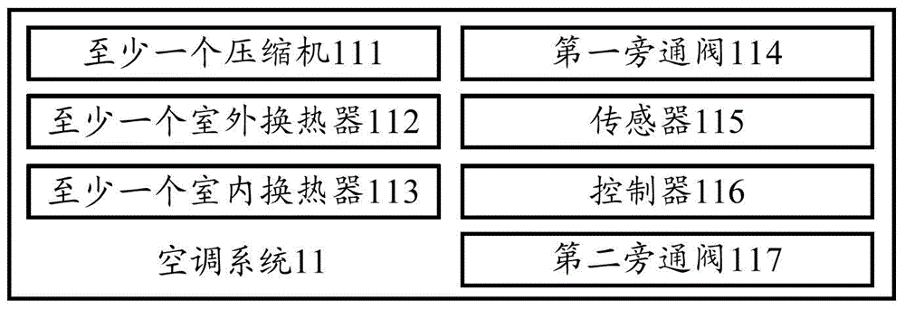
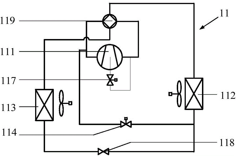
[0039] figure 1 with figure 2 A schematic diagram of an air conditioning system according to an embodiment of the present invention is shown.

[0040] Such as figure 1 As shown, an air condition...


PUM


Abstract

The invention provides an air conditioning system, an air conditioner, and a control method for the air conditioning system. The air conditioning system comprises one or more compressors, one or more outdoor heat exchangers, one or more indoor heat exchangers, first by-pass valves, second by-pass valves, sensors and controllers, wherein the first by-pass valves are arranged between the compressors and the outdoor heat exchangers; one end of each of the second by-pass valves is connected to the drainage outlet of the corresponding compressor, and the other ends of the second by-pass valves are connected to a return pipe of the air conditioner; the sensors are used for detecting the working parameters of the outdoor heat exchangers and/or the indoor heat exchangers, and sending the working parameters to the controllers; the controllers are used for adjusting the opening of the first by-pass valves. Through the technical scheme, the circular flow of the air conditioning system can be automatically adjusted according to the load of the system, the energy-saving operation of the system is achieved, and the problem that the air conditioning system is low in heating efficiency, frosted and defrosted, which is caused by the fact that in a system heating mode, the outdoor environment temperature is too low is solved.

Description

technical field [0001] The present invention relates to the technical field of air conditioning, in particular to an air conditioning system, an air conditioner and a control method for the air conditioning system. Background technique [0002] When the outdoor ambient temperature is too low or the outdoor air humidity is high, common household air conditioners or commercial large-scale central air conditioners may cause problems such as a drop in evaporation temperature of the air conditioning system, low heating efficiency, and frosting when heating. For most of the system, reverse cycle defrosting is adopted, and four-way valve reverse cycle defrosting will cause problems such as oil rush, system pressure difference changes, and system reliability reduction. At the same time, the outdoor ambient temperature and air humidity cannot be artificially changed and even if they are changed The outdoor environmental conditions also need to spend too much money, and it is impossib...

Claims


Application Information

Patent Timeline
Patent Type & Authority Applications(China)
IPC IPC(8): F24F1/00F24F11/00
CPCF24F1/0003F24F11/30F24F2110/00
Inventor 王飞陈得宗史作君张宝成王密
Owner GD MIDEA HEATING & VENTILATING EQUIP CO LTD
Why Eureka
Try Eureka