
Detection device for a confocal microscope

a detection device and confocal microscope technology, applied in the direction of beam/ray focussing/reflecting arrangement, instruments, electric discharge lamps, etc., can solve the problems of not being able to achieve uniform resolution capacity, several pinhole apertures must be regularly adjusted by users, and the resolution and detection efficiency cannot be optimized for one wavelength, etc., to achieve reliable beam expansion and illumination of the lens, simple and reliable wavelength-dependent beam expansion

Active Publication Date: 2007-09-04
LEICA MICROSYSTEMS CMS GMBH
View PDF2 Cites 0 Cited by
  • Summary
  • Abstract
  • Description
  • Claims
  • Application Information

AI Technical Summary

Benefits of technology

The present invention is a detection device that can achieve high resolution and detection efficiency with simple components, even with detection light having different wavelengths. The invention includes a means for wavelength-dependent illumination of the lens, which allows for constant resolution and detection efficiency regardless of the wavelength of the detection light. This means that multiple detection paths or pinhole apertures are not necessary, which reduces the cost of the detection device. The invention also eliminates the need for several detection wavelengths, which simplifies the operation of the detection microscope. Overall, the invention provides a detection device that is cost-effective and easy to operate with different detection light wavelengths.

Problems solved by technology

As a result, resolution and detection efficiency can only be optimized for one wavelength when using a pinhole aperture with a fixed diameter.
No uniform resolution capacity can be achieved, even when using several pinhole apertures for different detection paths or detection wavelengths, respectively, because dyes emit a detection band and not discrete wavelengths.
In addition to the inability to optimize resolution of detection bands emitted by dyes, in the latter case it is furthermore disadvantageous that several pinhole apertures must regularly be adjusted by the user.
This makes the detection device or a confocal microscope implemented with the detection device costly in terms of operation.

Method used


Image

  • Detection device for a confocal microscope
  • Detection device for a confocal microscope
  • Detection device for a confocal microscope

Examples


Embodiment Construction

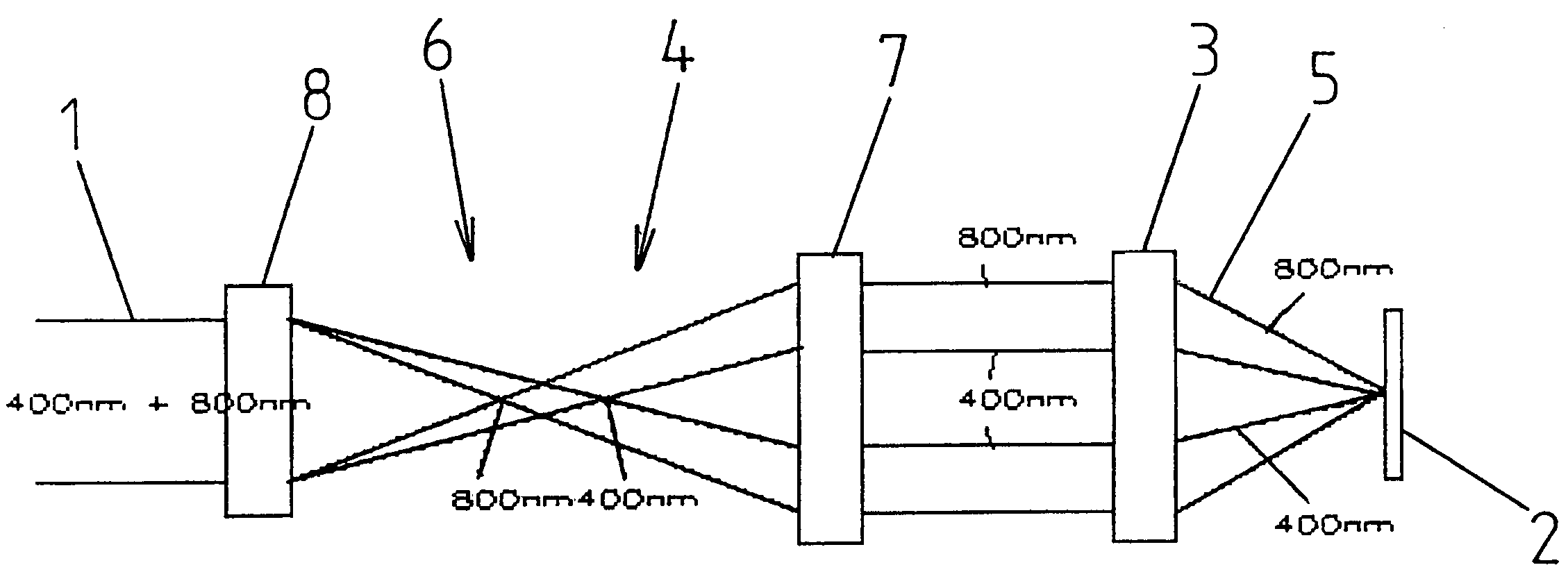
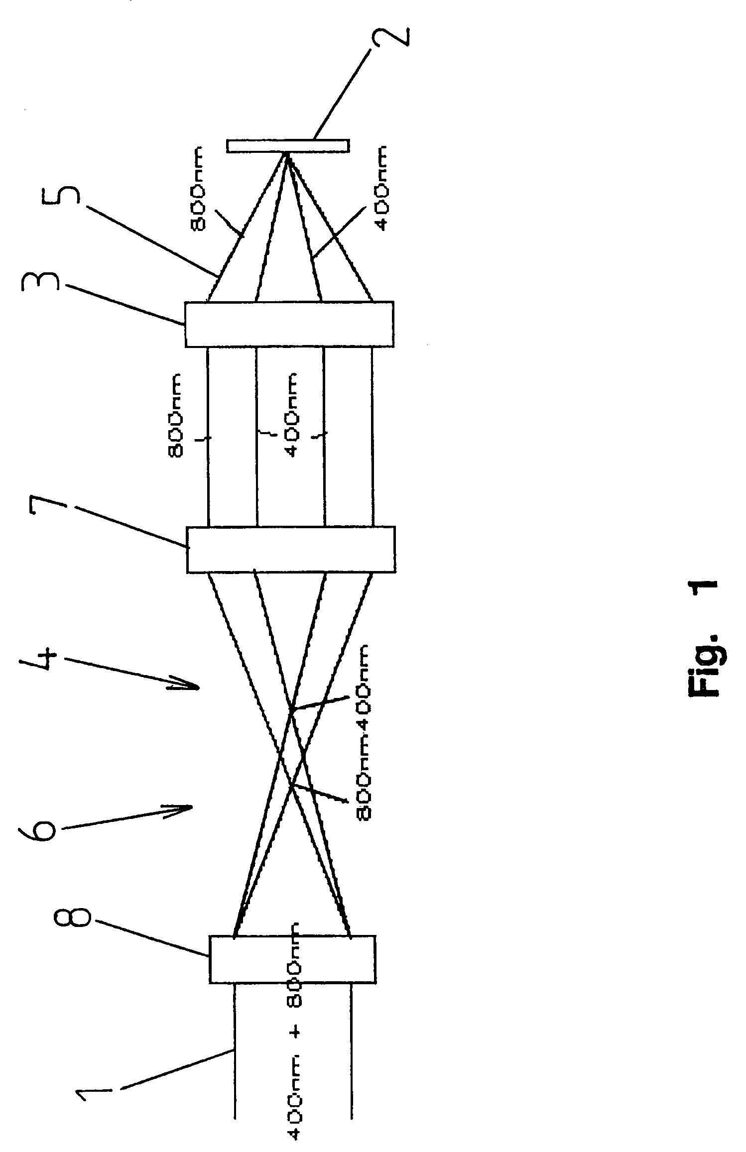
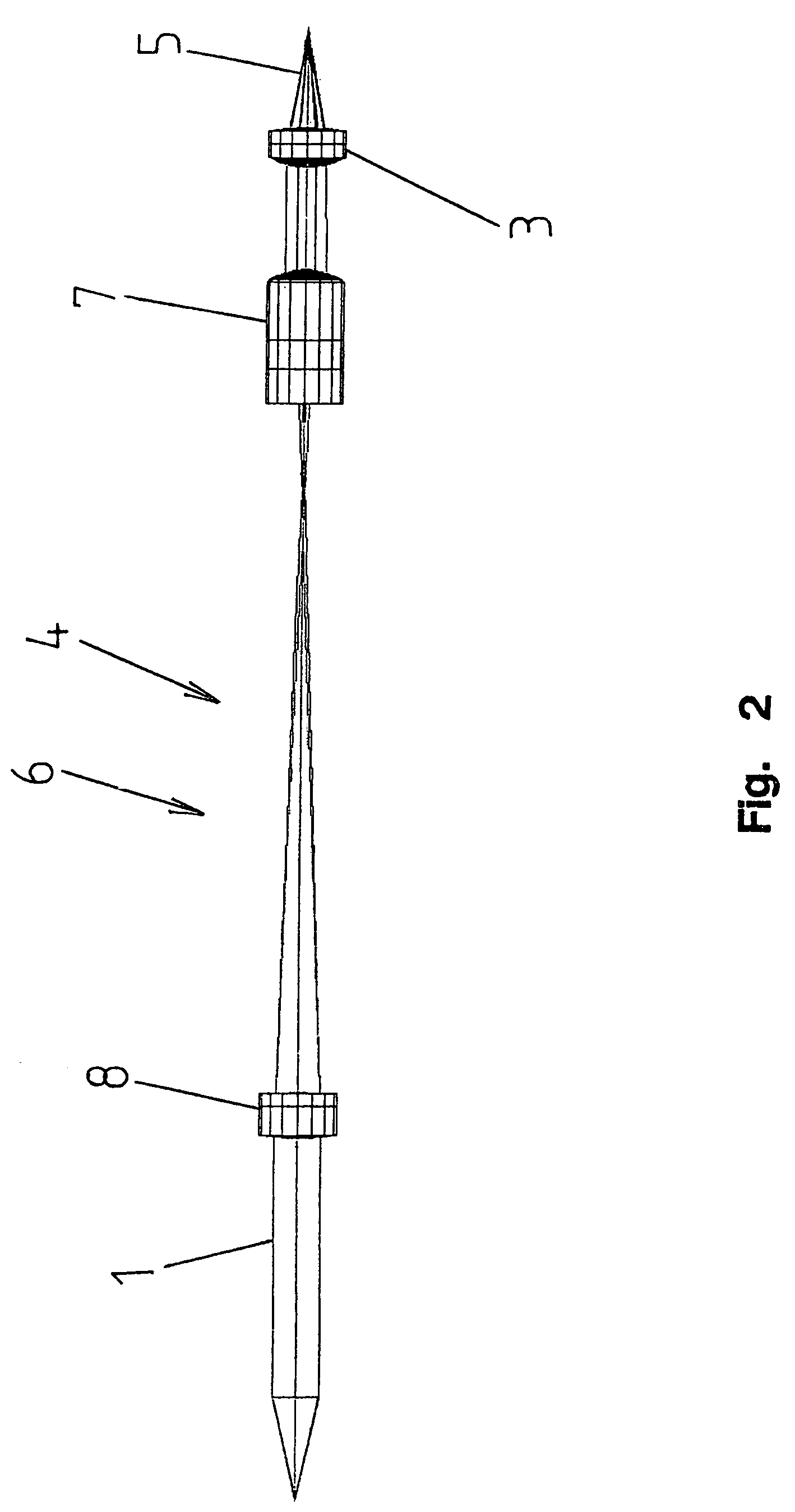
[0021]FIG. 1 shows a schematic representation of an embodiment of a detection device for an optical configuration according to the invention. The detection device can be used in particular within a confocal microscope. The detection device exhibits a detector that for the sake of clarity is not shown here, which can be implemented as a photomultiplier. Furthermore, the detection device exhibits a pinhole aperture 2 before the detector in a beam path 1 of a detection light, and a lens 3 arranged before the pinhole aperture 2 for focusing the detection light on the pinhole aperture 2. With regard to high resolution and detection efficiency even in the presence of detection light with varying wavelengths, a means 4 for illuminating the lens 3 dependent on wavelength is arranged in the beam path 1 before the lens 3. Illumination of the lens 3 can be specified such that the numerical aperture of the illuminating cone 5 generated by the lens 3 is largely proportional to the wavelength of ...


PUM


Abstract

A detection device for an optical configuration, in particular for a confocal microscope, with a detector, a pinhole aperture 2 arranged before the detector in a beam path 1 of the detection light, and a lens 3 for focusing the detection light on the pinhole aperture 2 arranged before the pinhole aperture 2, is implemented with regard to high resolution and detection efficiency even in the presence of varying wavelengths such that a means 4 for wavelength-dependent illumination of the lens 3 is arranged before the lens 3 in the beam path 1. Furthermore, a wavelength-dependent beam expander 6 as well as a confocal microscope with such a detection device are disclosed.

Description

RELATED APPLICATIONS[0001]This application claims priority to German application No. DE 10 2004 053 705.4, filed on Nov. 3, 2004, which is incorporated herein by reference in its entirety.BACKGROUND OF THE INVENTION[0002]The present invention relates a detection device for an optical configuration, in particular for a confocal microscope with a detector, a pinhole aperture located before the detector in a beam path of a detection light, and a lens located before the pinhole aperture to focus the detection light on the pinhole aperture. The present invention further relates to a beam expander and a confocal microscope that is dependent on a wavelength.SUMMARY OF THE INVENTION[0003]Detection devices of the aforementioned type are known from practice and exist in different embodiments. Such detection devices are used, among other applications, in confocal microscopes, particularly in confocal scanning microscopes. Here, the detection light is guided via a lens to the pinhole aperture a...

Claims


Application Information

Patent Timeline
Patent Type & Authority Patents(United States)
IPC IPC(8): G02B3/00H01J3/14
CPCG02B21/0024
Inventor SCHREIBER, FRANK
Owner LEICA MICROSYSTEMS CMS GMBH
Learn More