Eureka AIR delivers breakthrough ideas for toughest innovation challenges, trusted by R&D personnel around the world.

Printed Circuit Board And Probe Therewith

Active Publication Date: 2010-04-29
SAMSUNG MEDISON
View PDF3 Cites 18 Cited by
  • Summary
  • Abstract
  • Description
  • Claims
  • Application Information

AI Technical Summary

Benefits of technology

[0011]The present invention is conceived to solve the problem of the conventional technique as described above, and an aspect of the present invention is to provide an improved probe that can prevent deterioration of performance caused by defective connection between a piezoelectric layer and a printed circuit board (PCB).

Problems solved by technology

In such a probe, a bonding force between the piezoelectric device and the bonding surface of the PCB is low to cause unreliable bonding between the PCB and the piezoelectric layer, thereby deteriorating performance of the probe.

Method used


Image

  • Printed Circuit Board And Probe Therewith
  • Printed Circuit Board And Probe Therewith
  • Printed Circuit Board And Probe Therewith

Examples


Embodiment Construction

[0023]Exemplary embodiments of the present invention will now be described in detail with reference to the accompanying drawings. It should be noted that the drawings are not to precise scale and may be exaggerated in thickness of lines or size of components for descriptive convenience and clarity only. Furthermore, terms used herein are defined by taking functions of the present invention into account and can be changed according to the custom or intention of users or operators. Therefore, definition of the terms should be made according to overall disclosures set forth herein.

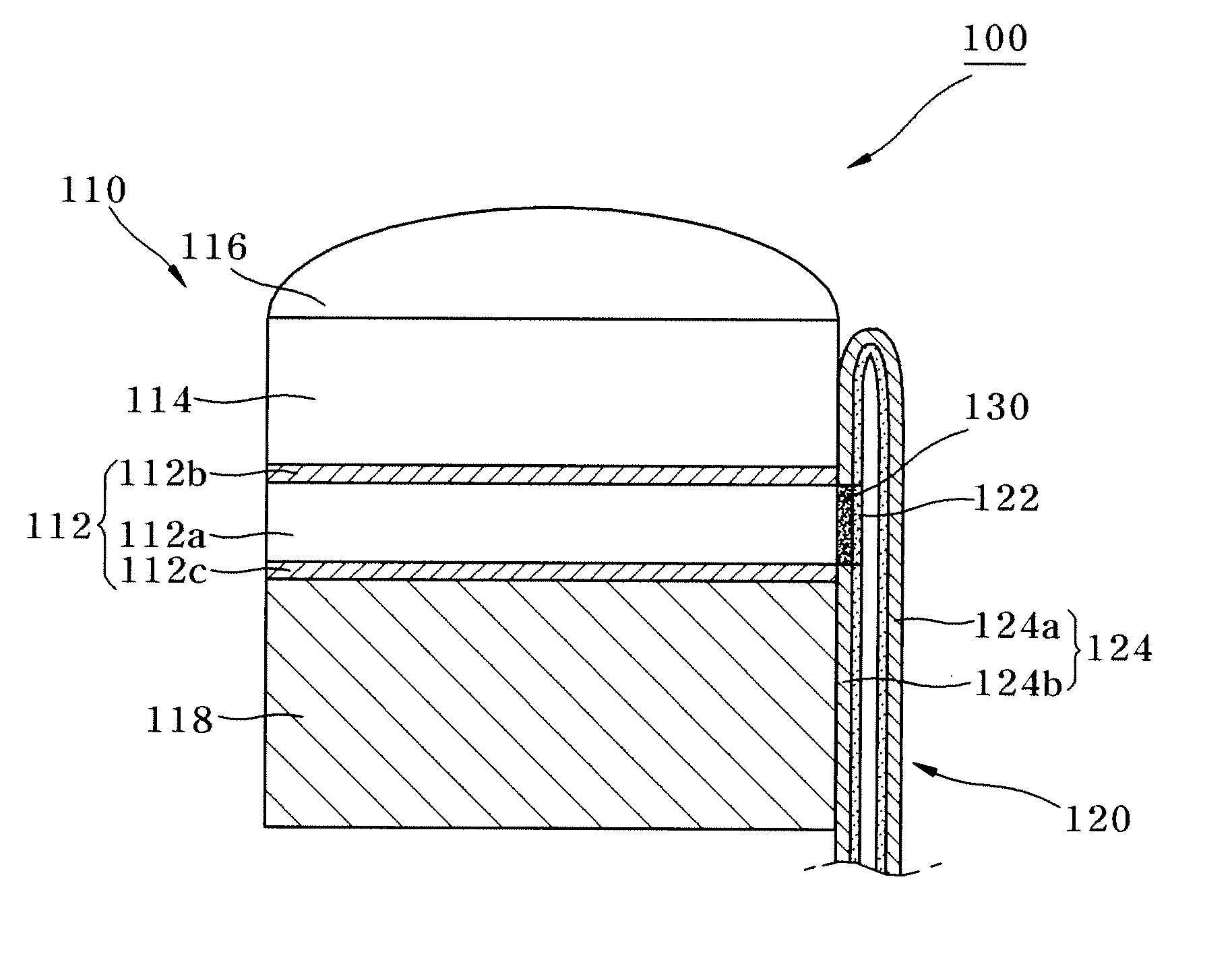
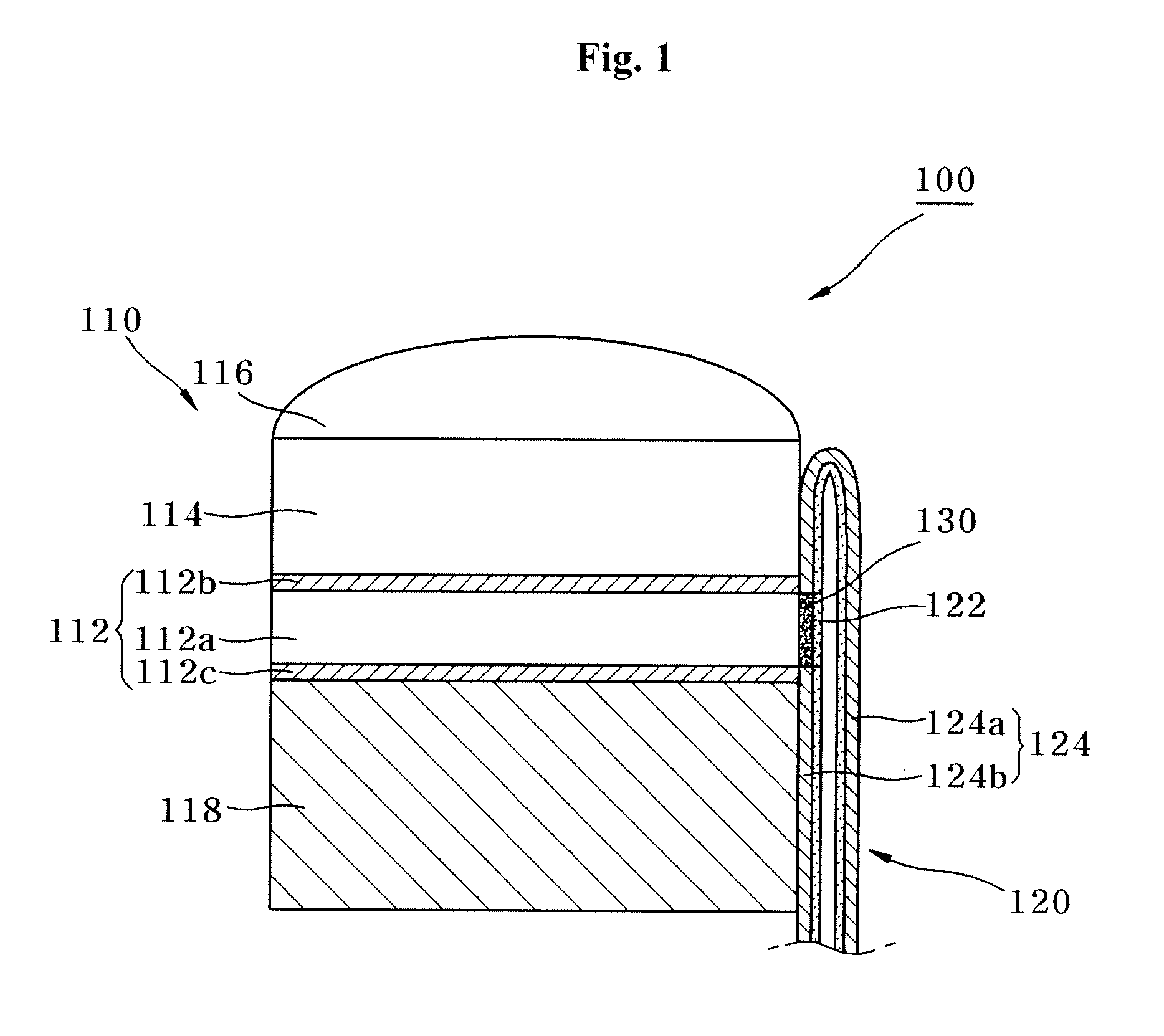
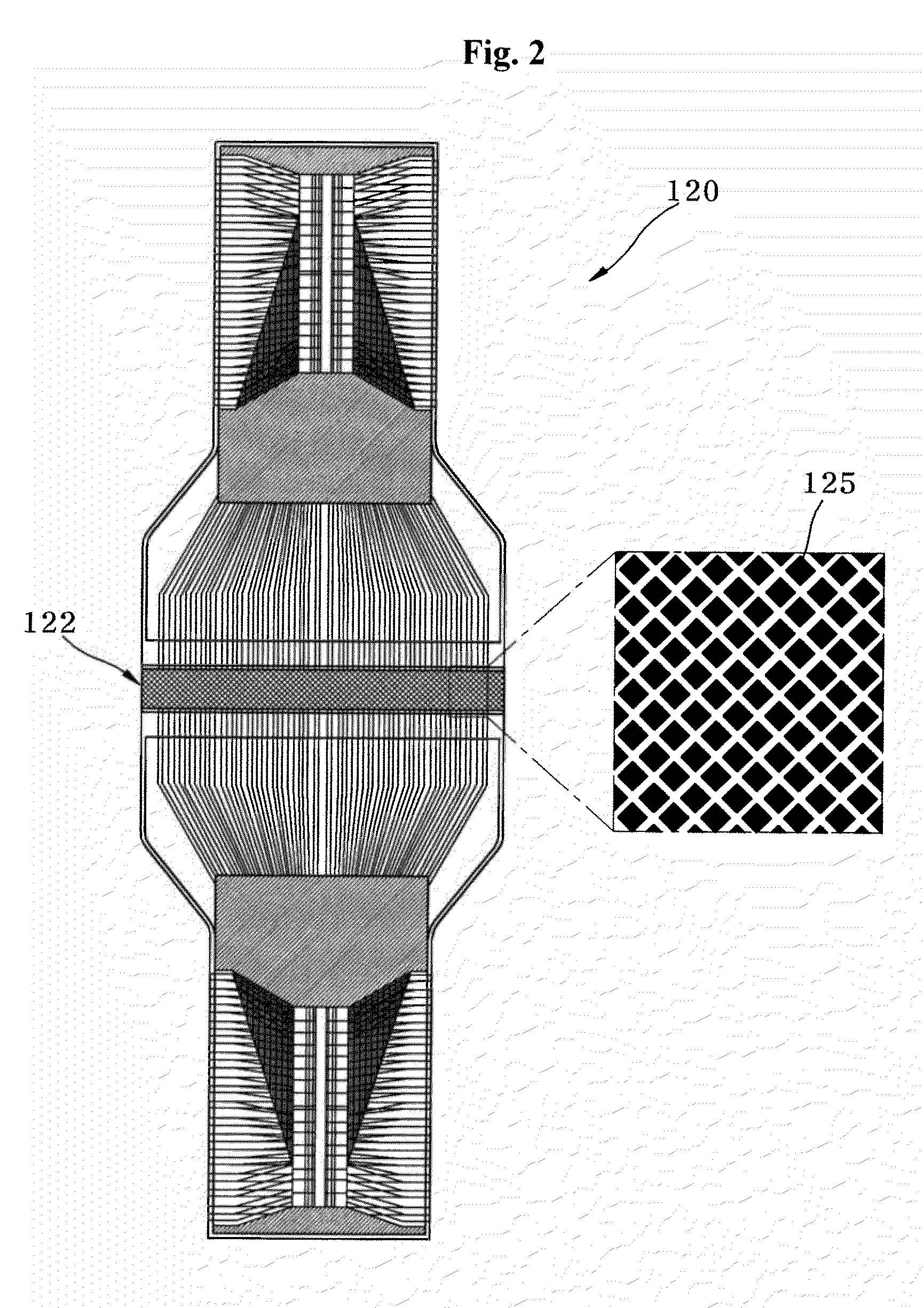
[0024]FIG. 1 is a schematic cross-sectional view of a probe according to an embodiment of the present invention, and FIG. 2 is a view of a PCB shown in FIG. 1.

[0025]Referring to FIGS. 1 and 2, a probe 100 according to the embodiment of the invention includes a transducer 110, a PCB 120, and a bonding member 130.

[0026]The transducer 110 transmits an ultrasound signal to a patient body and receives the ultrasou...


PUM


Abstract

Disclosed herein are a printed circuit board (PCB) and a probe including the same. The probe includes a transducer, a PCB having a pattern part contacting the transducer via face-to-face contact, and a bonding member bonding the transducer to the pattern part of the PCB. The bonding part of the PCB is provided with the pattern part to increase a bonding area of the bonding part and to allow the bonding member to contact not only a metal layer of the bonding part but also an electrical insulation part thereof, thereby improving a bonding force between the transducer and the PCB. As a result, the transducer can be reliably bonded to the PCB, so that performance of the transducer can be prevented from being deteriorated due to defective connection between the PCB and the transducer.

Description

CROSS-REFERENCE TO RELATED APPLICATIONS[0001]This application claims the benefit of Korean Patent Application No. 10-2008-0106259, filed on Oct. 29, 2008, the entire contents of which are incorporated by reference herein.BACKGROUND OF THE INVENTION[0002]1. Field of the Invention[0003]The present invention relates to a printed circuit board (PCB) and, more particularly, to a PCB and a probe including the same for use in an ultrasound system that generates internal images of a patient body with ultrasound waves.[0004]2. Description of the Related Art[0005]Generally, an ultrasound system refers to a non-invasive apparatus that irradiates an ultrasound signal from a surface of a patient body towards a target internal organ beneath the body surface and obtains an image of a monolayer or blood flow in soft tissue from information in the reflected ultrasound signal (ultrasound echo-signal). The ultrasound system has been widely used for diagnosis of the heart, the abdomen, the urinary orga...

Claims


Application Information

Patent Timeline
IPC IPC(8): H05K7/06
CPCA61B8/00A61B8/4483B06B1/0622H05K1/189H05K3/305A61B8/4494H05K2201/09681H05K2201/09781H05K2201/10083H05K2201/10462A61B8/4461H05K2201/055Y02P70/50G01N29/24
Inventor JIN, GIL JUPARK, JUNG LIMKIM, JAE YK
Owner SAMSUNG MEDISON
Why Eureka
Eureka Blog
Learn More