Semiconductor integrated circuit and information processing system
a technology of integrated circuit and information processing system, which is applied in the direction of pulse automatic control, pulse characteristics measurement, instruments, etc., can solve the problems of low detection accuracy, inability to stabilize the high-speed oscillator, and the technology of patent document 1 lacks reliability in the detection precision, so as to improve reliability, high detection reliability, and high detection reliability
- Summary
- Abstract
- Description
- Claims
- Application Information
AI Technical Summary
Benefits of technology
Problems solved by technology
Method used
Image
Examples
embodiment 1
1. Embodiment 1
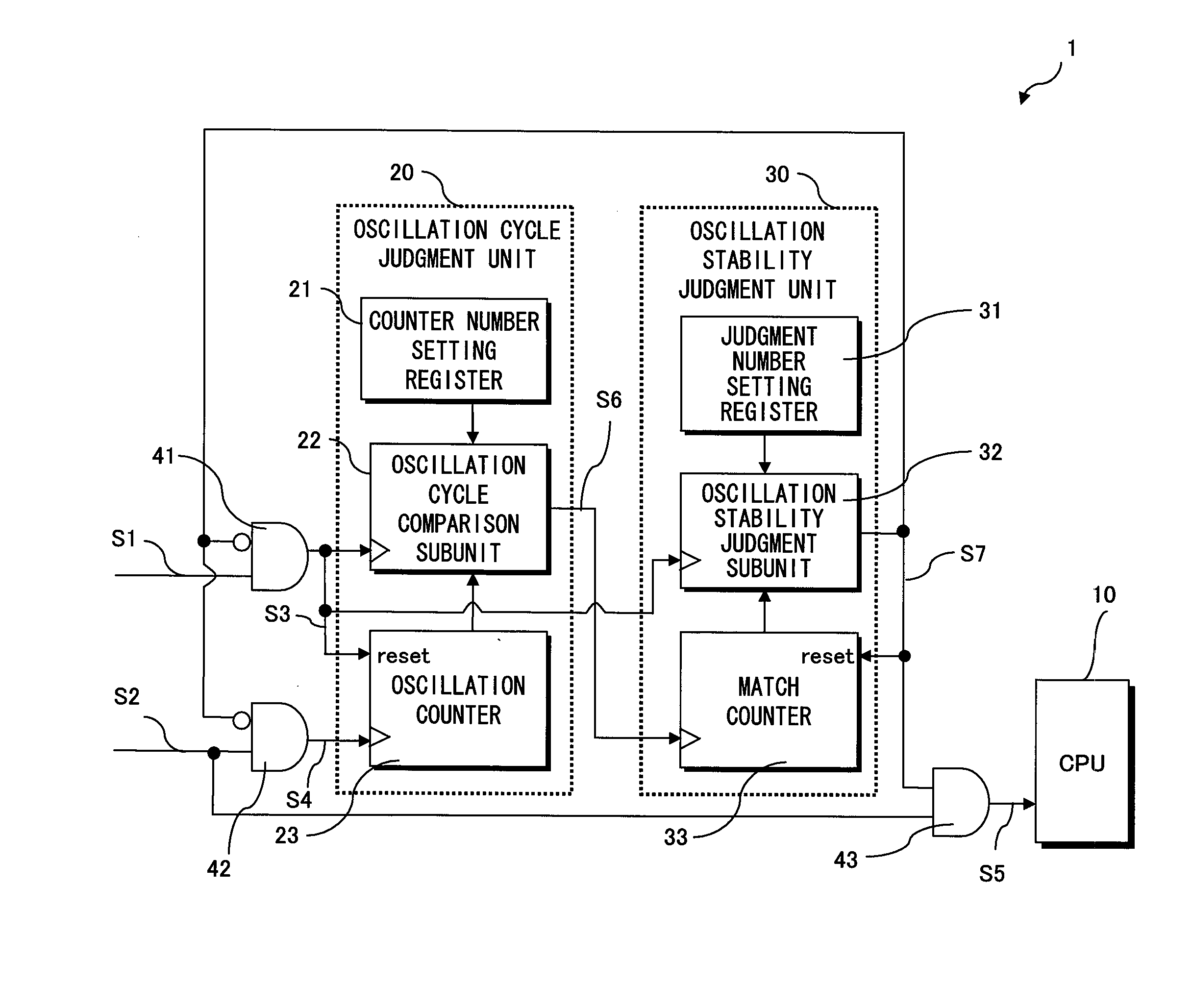
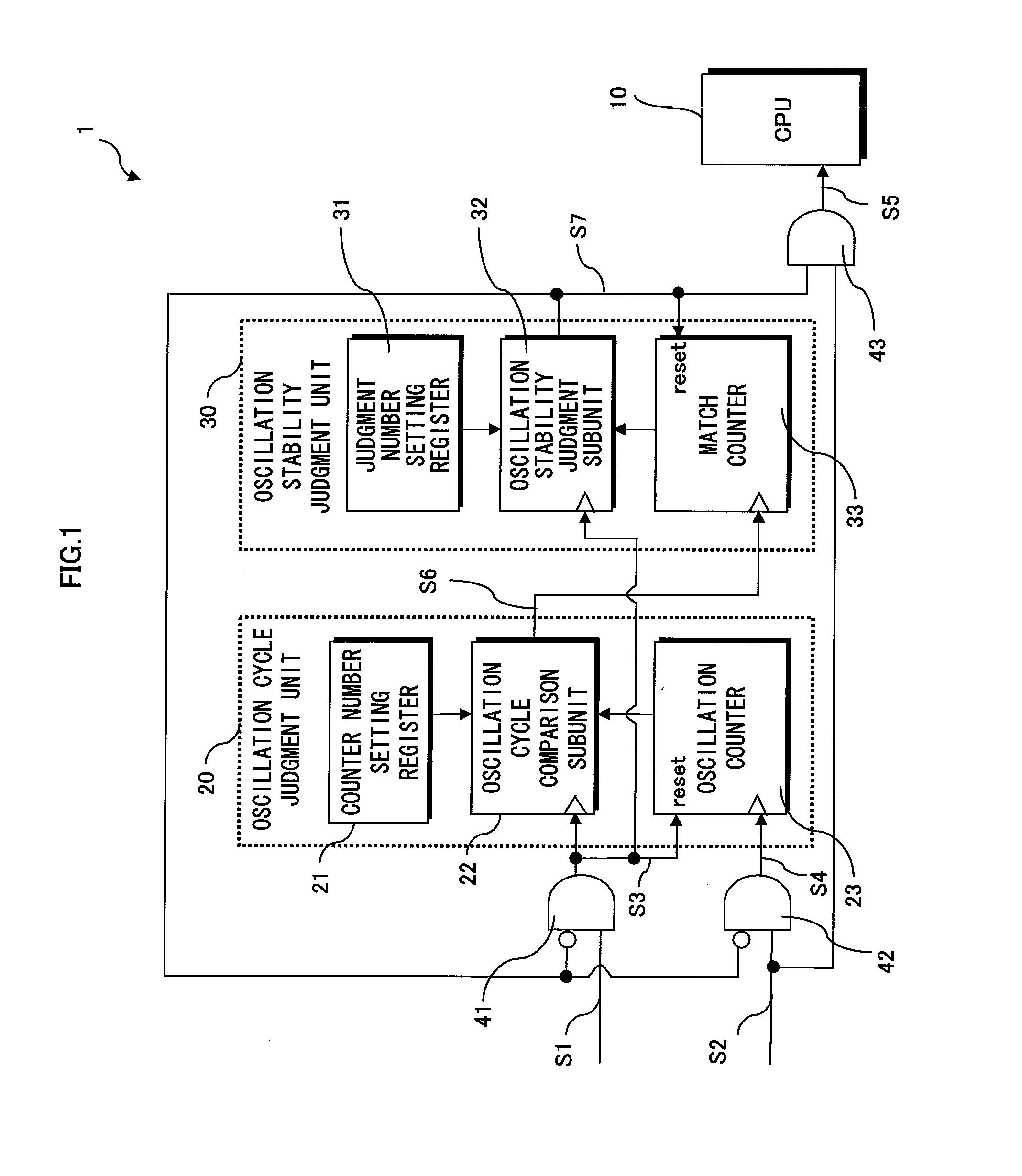
[0115]Below is a description of a semiconductor integrated circuit pertaining to the present invention with reference to the drawings.
[0116]1.1. Overview
[0117]The following briefly describes an overview of an information processing system including a semiconductor integrated circuit of the present invention.
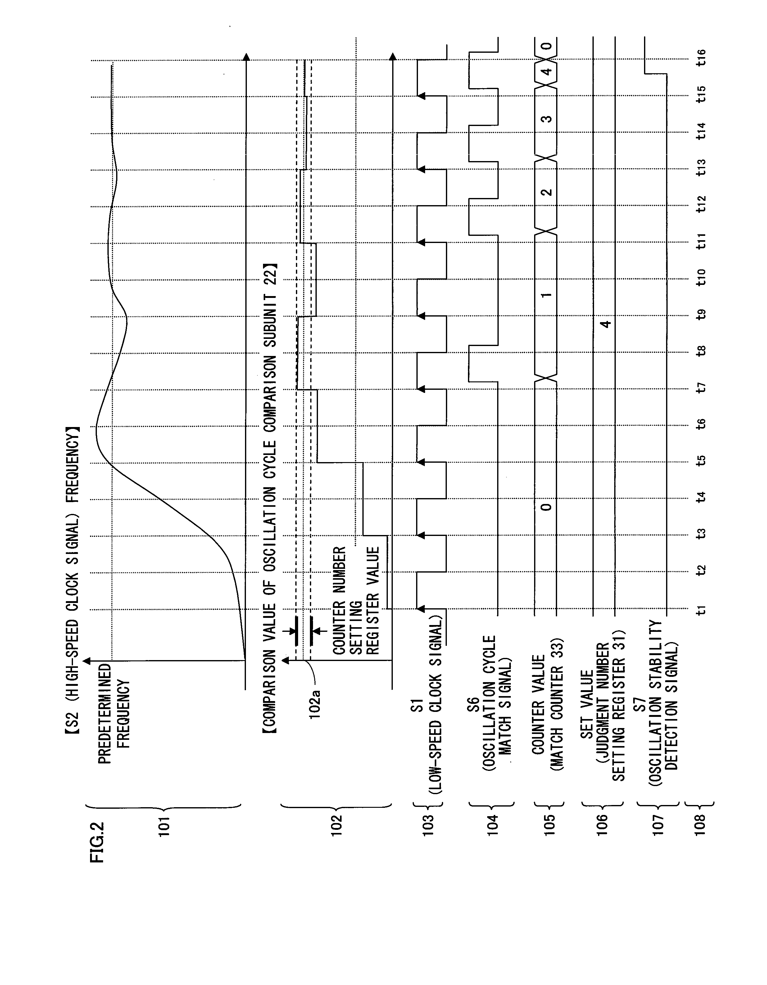
[0118]The information processing system includes a low-speed oscillator that cyclically generates a low-speed clock signal (clock pulse), and a high-speed oscillator that cyclically generates a high-speed clock signal (clock pulse). The information processing system also includes two operation modes, namely a normal mode and a standby mode, and switches between the normal mode and standby mode while operating.
[0119]In normal mode, the information processing system operates with use of the high-speed clock signal. In standby mode, the information processing system stops the oscillation of the high-speed oscillator, and operates with use of the low-speed clock signal...
embodiment 2
2. Embodiment 2
[0197]The following describes another embodiment of the present invention.
[0198]2.1. Overview
[0199]In the above-described technology, the semiconductor integrated circuit 1 detects that the high-speed clock signal is being generated stably, and thereafter the information processing system switches from standby mode to normal mode. However, if an abnormality occurs in the high-speed clock signal after the switch to normal mode, there is a risk that the information processing system will become unstable. In view of this, the present embodiment further provides an oscillation cycle monitor circuit 50 as shown in FIG. 3.
[0200]After the semiconductor integrated circuit has made the detection, the oscillation cycle monitor circuit 50 checks, according to a predetermined timing (e.g., periodically), whether the oscillation of the high-speed oscillator is stable.
[0201]2.2. Structure
[0202]FIG. 3 is a functional block diagram showing the structure of a semiconductor integrated ...
embodiment 3
3. Embodiment 3
[0281]The following describes another embodiment of the present invention.
[0282]3.1. Overview
[0283]FIG. 6 is a functional block diagram showing the structure of a semiconductor integrated circuit 1c of embodiment 3.
[0284]The following description focuses on differences from embodiment 1.
[0285]Embodiment 3 differs from embodiment 1 in that the semiconductor integrated circuit 1c includes an oscillation cycle measurement start timing control unit 60.
[0286]Also, the semiconductor integrated circuit 1c includes a clock gating circuit 44 instead of the clock gating circuit 41, and a clock gating circuit 45 instead of the clock gating circuit 42.
[0287]A description of the functions of the counter number setting register 21, the judgment number setting register 31, and the match counter 33 and the connections therebetween has been omitted since they are the same as in embodiment 1.
[0288]The oscillation cycle measurement start timing control unit 60 counts and stores the numb...
PUM
 Abstract
Description
Claims
Application Information
 - R&D
- Intellectual Property
- Life Sciences
- Materials
- Tech Scout
- Unparalleled Data Quality
- Higher Quality Content
- 60% Fewer Hallucinations
Browse by: Latest US Patents, China's latest patents, Technical Efficacy Thesaurus, Application Domain, Technology Topic, Popular Technical Reports.
© 2025 PatSnap. All rights reserved.Legal|Privacy policy|Modern Slavery Act Transparency Statement|Sitemap|About US| Contact US: help@patsnap.com


