Iterative test generation and diagnostic method based on modeled and unmodeled faults

a fault and model technology, applied in the field of design automation of very large scale integrated circuits, can solve the problems of large and insufficient pattern sets with ineffective diagnostic resolution, inability to accurately identify defects, and inability to use effective test patterns and precise diagnostic methodologies, so as to improve the tester's time and improve the fault resolution. , the effect of high confiden

Inactive Publication Date: 2008-05-15
IBM CORP
View PDF5 Cites 21 Cited by
  • Summary
  • Abstract
  • Description
  • Claims
  • Application Information

AI Technical Summary

Benefits of technology

[0028]The method of the present invention achieves high confidence fault detection tests which are identified by using standard diagnostic techniques and generating N-detect set of patterns for modeled faults associated with the identified nets. The tests are than re-applied using these focused patterns and corresponding failing passing responses logged and utilized for intermediate diagnostic analysis. The above process is then repeated until a desired diagnostic confidence level is achieved. The high diagnostic resoluti

Problems solved by technology

A problem often encountered when testing and subsequently diagnosing VLSI devices is the availability of effective test patterns and a precise diagnostic methodology to pinpoint the root cause of a broad range of modeled and unmodeled faults.
The rapid integration growth of VLSI devices with their associated high circuit performance and complex semiconductor processes has intensified old and introduced new types of defects.
This defect diversity, accompanied by the limited number of fault models, usually results in large and insufficient pattern sets with ineffective diagnostic resolution.
Oftentimes, the resultant diagnostic callout does not give a sufficiently clear indication of the fault location.
Physical defects can manifest themselves in many ways and often enough do not match any fault model.
Conventio

Method used


Image

  • Iterative test generation and diagnostic method based on modeled and unmodeled faults
  • Iterative test generation and diagnostic method based on modeled and unmodeled faults
  • Iterative test generation and diagnostic method based on modeled and unmodeled faults

Examples


Embodiment Construction

[0038]A preferred embodiment of the present invention is described hereinafter illustrating several system components that tightly and interactively couple the test pattern generation and tester execution process.

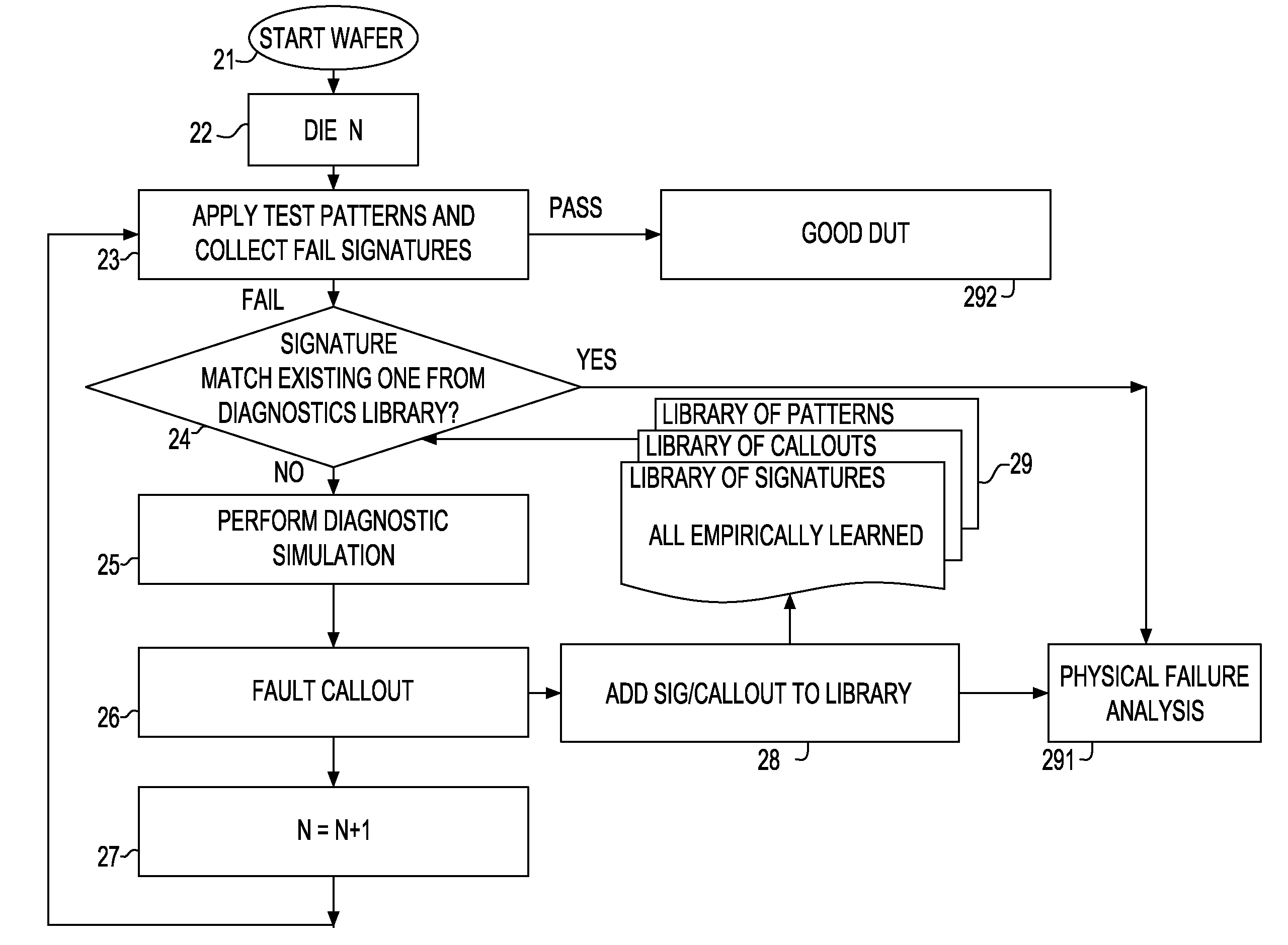
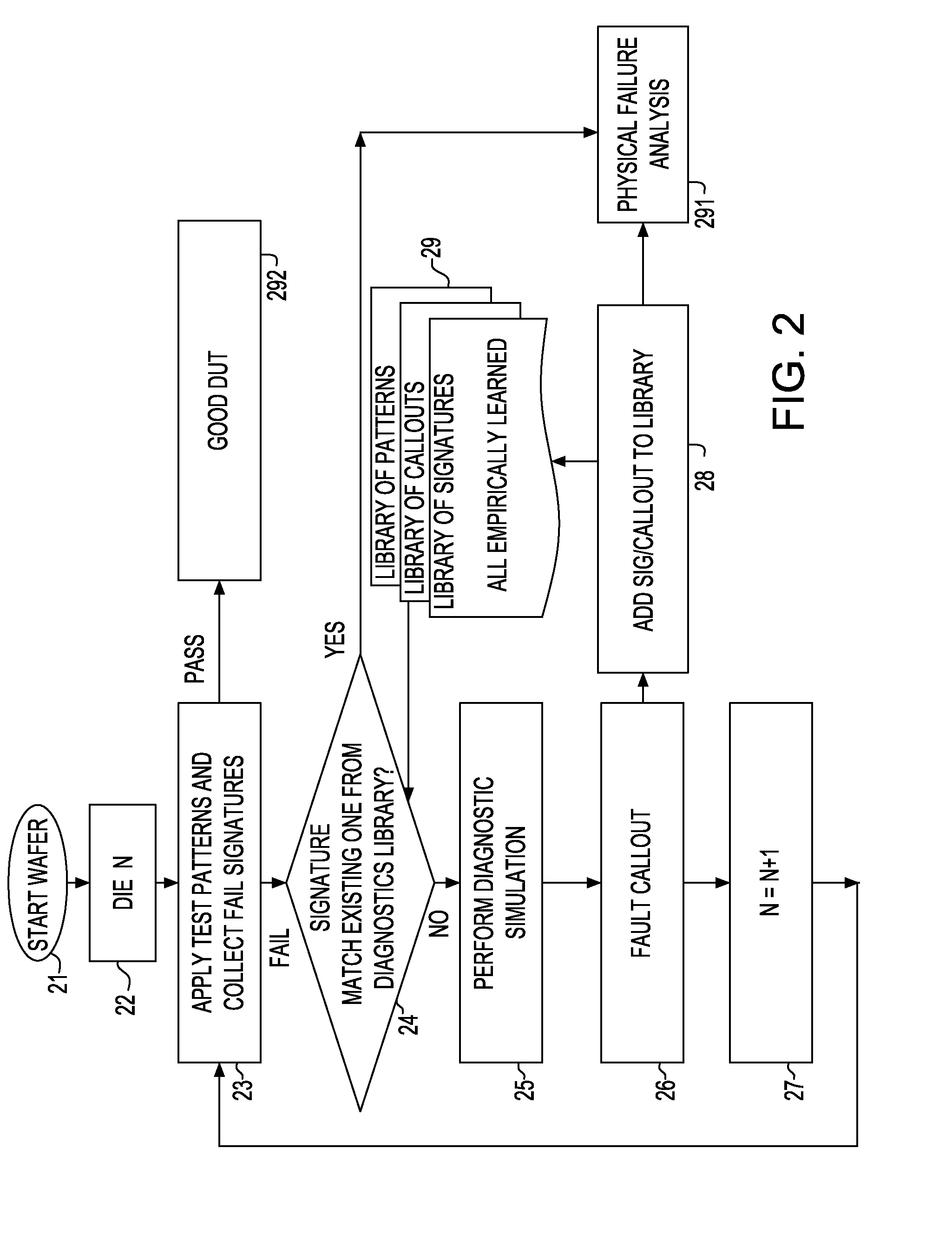
[0039]Referring to FIGS. 2-5, the flow and functional components of the Iterative Diagnostic Process are illustrated. The test generation, fault simulation and diagnostic simulation blocks have inputs from the logic design and fault models. The test generation block provides manufacturing test patterns and custom interactive diagnostic patterns, labeled N-detect patterns in the respective figures. Other special purpose algorithms are also invoked to generate custom patterns, as will be described hereinafter.

[0040]The iterative diagnostic and test execution process invokes an Adaptive Fail Device Specific Iterative Process multiple times until a desired diagnostic resolution is achieved.

[0041]The process steps preferably include:[0042]1. Identifying the highest confidence ne...


PUM


Abstract

A diagnostic and characterization tool applicable to structural VLSI designs to address problems associated with fault tester interactive pattern generation and ways of effectively reducing diagnostic test time while achieving greater fail resolution. Empirical fail data drives the creation of adaptive test patterns which localize the fail to a precise location. This process iterates until the necessary localization is achieved. Both fail signatures and associated callouts as well as fail signatures and adaptive patterns are stored in a library to speed diagnostic resolution. The parallel tester application and adaptive test generation provide an efficient use of resources while reducing overall test and diagnostic time.

Description

FIELD OF THE INVENTION[0001]The present invention relates to the field of Design Automation of Very Large Scale Integrated (VLSI) circuits, and more particularly, to a method of testing and subsequent diagnosing failures based on a broad range of modeled and unmodeled faults.BACKGROUND OF THE INVENTION[0002]A problem often encountered when testing and subsequently diagnosing VLSI devices is the availability of effective test patterns and a precise diagnostic methodology to pinpoint the root cause of a broad range of modeled and unmodeled faults. The rapid integration growth of VLSI devices with their associated high circuit performance and complex semiconductor processes has intensified old and introduced new types of defects. This defect diversity, accompanied by the limited number of fault models, usually results in large and insufficient pattern sets with ineffective diagnostic resolution.[0003]Identifying faults and pinpointing the root cause of the problem in a large logic stru...

Claims


Application Information

Patent Timeline
IPC IPC(8): G01R31/28G06F11/00
CPCG01R31/318342G06F11/261G01R31/318364
Inventor KUSKO, MARY P.FLEISCHMAN, THOMAS J.MOTIKA, FRANCOTRAN, PHONG T.
Owner IBM CORP
Why Eureka
Try Eureka