
Scintillation detector and associated scintillation detector ring and method

a scintillation detector and detector ring technology, applied in the direction of instruments, radiation measurement, measurement devices, etc., can solve the problems of inability to accurately assign lor, pet technology still has some limitations, error or blur in the reconstructed image,

Active Publication Date: 2022-07-12
THE ARIZONA BOARD OF REGENTS ON BEHALF OF THE UNIV OF ARIZONA
View PDF11 Cites 2 Cited by
  • Summary
  • Abstract
  • Description
  • Claims
  • Application Information

AI Technical Summary

Benefits of technology

This approach improves spatial and depth-of-interaction resolution while maintaining energy resolution and detection efficiency, reducing the number of readout channels and manufacturing costs, and enhancing the capability to accurately determine gamma-ray interaction positions.

Problems solved by technology

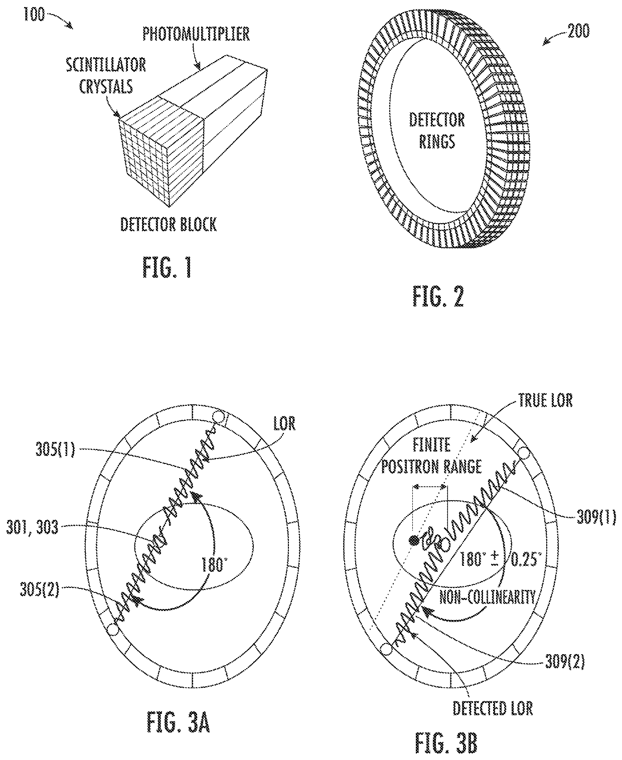
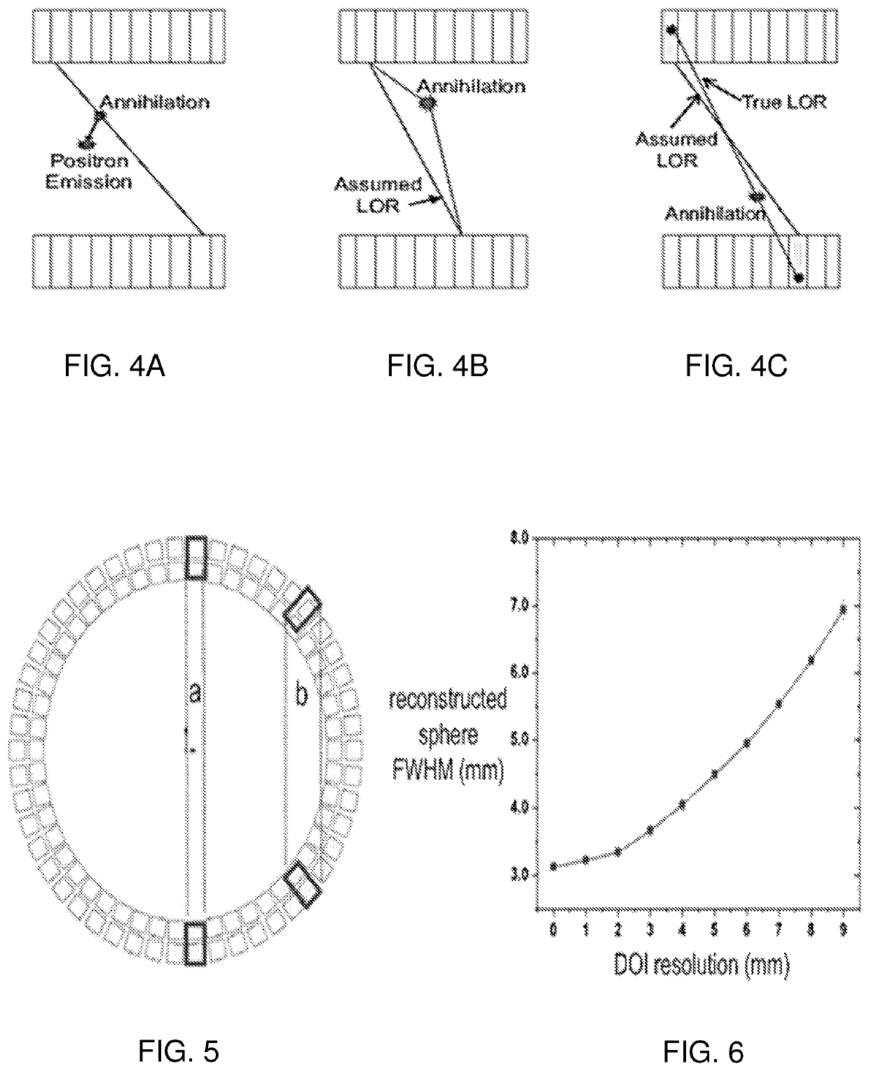
However, this may result in an incorrectly assigned LOR due to parallax error.
However, PET technology still has some limitations.
Since the annihilation position is different from the radioactive isotope's position because the positron travels a small distance before it combines with an electron (positron range effect), there is error or blur in the reconstructed image.
Limitation 2: Making the pixelated crystal's cross section small can be very challenging.
Due to the high energy of gamma-ray photons, they are very difficult to stop.
However, this makes the pixelated crystal's aspect ratio low.
The smaller the pixel's pitch size, the larger the number of reflections required for a photon to travel to the photon sensors, which will decrease the light output amount due to the losses from reflections.
Limitation 4: The cost of manufacturing pixelated crystals is extremely high.
Since pixelated crystals need special surface treatment (insulating, polishing) between individual pixels, the cost of manufacturing such crystals is high.
Moreover, if the pixels are smaller than around 1 mm, the difficulty in special treatments drives the cost even higher.
This gap will decrease the detection efficiency of the detector to gamma-ray photons.

Method used


Image

  • Scintillation detector and associated scintillation detector ring and method
  • Scintillation detector and associated scintillation detector ring and method
  • Scintillation detector and associated scintillation detector ring and method

Examples


example 1

[0099]An analysis of side readouts of monolithic scintillation crystals. A method of using the side surfaces of a thin monolithic scintillation crystal for reading out scintillation photons is described. A Monte-Carlo simulation was carried out for an LYSO crystal of 50.8 mm×50.8 mm×3 mm with five silicon photomultipliers attached on each of the four side surfaces. With 511 keV gamma-rays, X-Y spatial resolution of 2.10 mm was predicted with an energy resolution of 9%. The addition of optical barriers was also explored to improve the X-Y spatial resolution. An X-Y spatial resolution of 786 μm was predicted with an energy resolution of 9.2%. Multiple layers may be stacked together and readout channels may be combined. Depth of interaction information (DOI) may be directly read out. This method provides an attractive detector module design for positron emission tomography (PET).

[0100]FIG. 13 illustrates a scintillation event 1301 (or equivalently, a gamma-ray interaction event) within...

example 2

[0133]Simulation of a CsI / LYSO Detector Layer. This section describes simulation of crystals that that were tested experimentally. The geometry of the scintillation crystal was set as 27.4 mm×27.4 mm×3 mm. Sixteen SiPMs were attached to the edges of the scintillation crystal with 4 SiPMs on each edge. Several factors influencing the spatial resolution were studied:[0134]I. gamma-ray photon energy and scintillator material (662 keV for CsI(TI) vs 511 keV for LYSO);[0135]II. optical barriers (with / without);[0136]III. optical-gel & SiPM-window refractive indices (1.5 vs 1.82).

The dark-count rate was set to 2 MHz / SiPM in accordance with the Hamamatsu S13360-6050 PE MPPC data sheet. The readout shaping time was set to 4 μs for CsI(TI) and 150 ns for LYSO, based on their published decay times (Mao R, Zhang L, Zhu, R. Optical and Scintillation Properties of Inorganic Scintillators in High Energy Physics. IEEE Transactions on Nuclear Science. 2008; 55 (4): 2425-2431). The optical-gel / SiPM-w...

experimental verification

[0139]FIG. 40 includes photographs of components of a prototype detector 4001 and 4002. The prototype detector includes the following components, labelled (a) through (e) in FIG. 40:[0140](a) Sixteen Hamamatsu S13360-6050PE MPPCs (SiPMs);[0141](b) CsI(TI) scintillation crystal: CsI(TI) crystal of dimension 27.4 mm×27.4 mm×3 mm (obtained from Proteus, without mechanical holes as in detector 4001, and with mechanical holes, as in detector 4002);[0142](c) pre-amplifier circuit;[0143](d) amplifier and analog-to-digital-converting circuit;[0144](e) FPGA data acquisition circuit (AiT 16-channel-readout circuit).

The photograph labelled (f) is prototype detector 4001 or 4002.

[0145]The scintillator was chosen to be CsI(TI) for convenience (no background activity from the crystal and low hygroscopicity). The MDRFs were acquired by scanning the detector with a crossed-slit-collimated beam of 662 keV photons from a 137Cs source. The beam size on the detector surface was measured to be about 0.4...


PUM


Abstract

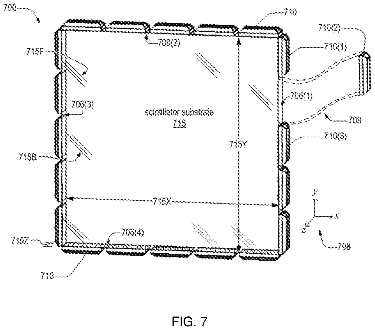
The invention provides a novel arrangement of photon sensors on a scintillation-crystal based gamma-ray detector that takes advantage of total internal reflection of scintillation light within the scintillation detector substrate. The present invention provides improved spatial resolution including depth-of-interaction (DOI) resolution while preserving energy resolution and detection efficiency, which is especially useful in small-animal or human positron emission tomography (PET) or other techniques that depend on high-energy gamma-ray detection. Moreover, the new geometry helps reduce the total number of readout channels required and eliminates the need to do complicated and repetitive cutting and polishing operations to form pixelated crystal arrays as is the standard in current PET detector modules.

Description

CROSS REFERENCE TO RELATED APPLICATIONS[0001]This application U.S. National Stage Application filed under 35 U.S.C. § 371 of International Application No. PCT / US2017 / 058501, filed Oct. 26, 2017, which claims the benefit of claims priority from United States Provisional Patent Application number 62 / 414,469 filed Oct. 28, 2016. Both of these applications are hereby incorporated by reference in their entireties.STATEMENT REGARDING FEDERALLY SPONSORED RESEARCH OR DEVELOPMENT[0002]This invention was made with government support under Grant No. P41 EB002035, awarded by NIH. The government has certain rights in the invention.BACKGROUND OF THE INVENTION[0003]Positron Emission Tomography (PET) has become a mature and reliable technology. It has broad applications in neurology and oncology due to its ability to monitor metabolism of glucose and the uptake of other targeting radiotracers in specific organs and tissues. Compared with other alternative options (functional MRI, CT, and SPECT), th...

Claims


Application Information

Patent Timeline
Patent Type & Authority Patents(United States)
IPC IPC(8): G01T1/29
CPCG01T1/2985G01T1/20183G01T1/20187G01T1/20186G01T1/20181G01T1/20185G01T1/20182
Inventor FURENLID, LARSLI, XIN
Owner THE ARIZONA BOARD OF REGENTS ON BEHALF OF THE UNIV OF ARIZONA
Learn More