Numerical control system velocity planning method based on fractional calculus

A technology of fractional calculus and speed planning, which is applied in general control systems, control/regulation systems, digital control, etc., can solve problems such as sudden acceleration changes, complex programming, and severe vibration of machine tools, and achieve smooth results

Inactive Publication Date: 2015-09-30
HARBIN INST OF TECH
View PDF3 Cites 9 Cited by
  • Summary
  • Abstract
  • Description
  • Claims
  • Application Information

AI Technical Summary

Problems solved by technology

[0003] The purpose of the present invention is to solve the existing speed planning method that causes severe vibration of the machine tool, huge amount of calc

Method used


Image

  • Numerical control system velocity planning method based on fractional calculus
  • Numerical control system velocity planning method based on fractional calculus
  • Numerical control system velocity planning method based on fractional calculus

Examples


specific Embodiment approach 1

[0024] Specific implementation mode one: a kind of speed planning method of numerical control system based on fractional calculus in this implementation mode is specifically prepared according to the following steps:

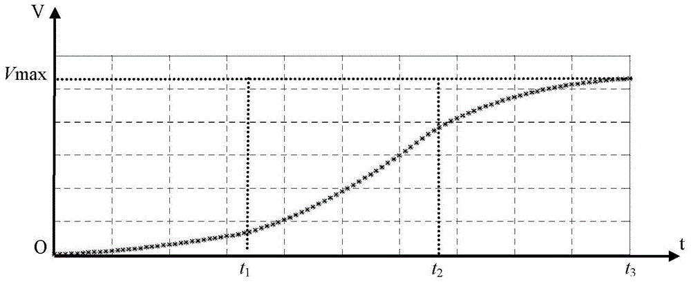
[0025] A numerical control system speed planning method based on fractional calculus uses the memory characteristics of fractional calculus to perform a fractional order integration on the predefined nominal acceleration to obtain a smooth acceleration and deceleration speed planning curve

[0026] Step 1, according to the controlled object motion time t, utilize the continuous function y=f(t) to derive the fractional derivative:

[0027] D t α c f ( t ) = lim h → 0 1 h α ...

specific Embodiment approach 2

[0040] Specific embodiment two: the difference between this embodiment and specific embodiment one is: in step one, according to the controlled object motion time t, utilize continuous function y=f (t), deduce the concrete process of fractional order derivative as:

[0041] (1) For the continuous function y=f(t), according to the classic derivation formula, the first-order derivation formula of the function y=f(t) is:

[0042] f ′ ( t ) = d f d t = lim h → 0 f ( t ) - f ( t - h ) ...

specific Embodiment approach 3

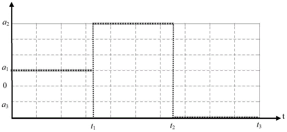
[0055] Specific embodiment three: the difference between this embodiment and specific embodiment one or two is: in step three, let α<0, the mathematical expression of the nominal acceleration defined in step two is:

[0056] a ( t ) = a 1 0 ≤ t t 1 a 2 t 1 ≤ t t 2 ...


PUM


Abstract

The invention relates to numerical control system velocity planning methods, in particular to a numerical control system velocity planning method based on fractional calculus, and aims to solve problems that existing velocity planning methods cause violent vibration of a machine tool, are large in calculated amount and complex in programming, have sudden acceleration change and produce rigid impact. The method comprises steps as follows: 1, a continuous function y=f(t) is used for deducing a fractional derivative; 2, nominal acceleration corresponding to t1, t2 and t3 are solved to be a1, a2 and a3 respectively; 3, a required acceleration section velocity planning curve is acquired; 4, the total displacement increment is calculated; 5, the displacement is solved to be D(m) according to a formula (3); 6, a controlled object begins to decelerate from the ith step of a deceleration point until the velocity is 0 when not reaching the maximum velocity Vmax; 7, the controlled object begins to decelerate from the jth step of the deceleration point until the velocity is 0; 8, the controlled object decelerates to the velocity 0 according to an S-like curve and the like. The method is applied to the field of numerical control system velocity planning.

Description

technical field [0001] The invention relates to a numerical control system speed planning method, in particular to a numerical control system speed planning method based on fractional calculus. Background technique [0002] Speed ​​planning is the core technology of CNC system. Commonly used speed planning methods include trapezoidal speed planning method, S-curve speed planning method, exponential speed planning method, etc. Although the trapezoidal speed planning method has a small amount of calculation and simple programming, there is a phenomenon of sudden acceleration and deceleration during the acceleration and deceleration phase, resulting in severe vibration of the machine tool, which is not suitable for high-speed and high-precision machining. The commonly used S-curve speed planning method controls the sudden change of acceleration by limiting the jerk. However, the traditional S-curve speed planning method uses polynomial representation to divide the entire speed...

Claims


Application Information

Patent Timeline
IPC IPC(8): G05B19/416
CPCG05B19/416G05B2219/43065
Inventor 孙光辉刘小磊胡延旭周承邦郑辉吴庭丞杨玉梁许林杨
Owner HARBIN INST OF TECH
Why Eureka
Try Eureka