
Coplanar waveguide bandstop filter based on a novel split-ring resonator structure

A split resonant ring and band-stop filter technology, which is applied in the microwave field, can solve problems such as not being suppressed, and achieve the effect of frequency selectivity improvement, widening bandwidth, and improving out-of-band performance

Active Publication Date: 2018-02-06
NANJING UNIV OF POSTS & TELECOMM
View PDF3 Cites 0 Cited by
  • Summary
  • Abstract
  • Description
  • Claims
  • Application Information

AI Technical Summary

Problems solved by technology

But the circuit has higher harmonics out of band, which are not well suppressed

Method used


Image

  • Coplanar waveguide bandstop filter based on a novel split-ring resonator structure
  • Coplanar waveguide bandstop filter based on a novel split-ring resonator structure
  • Coplanar waveguide bandstop filter based on a novel split-ring resonator structure

Examples


Embodiment Construction

[0019] Below in conjunction with accompanying drawing, technical scheme of the present invention is described in further detail:

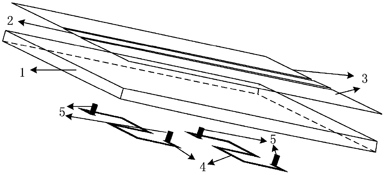
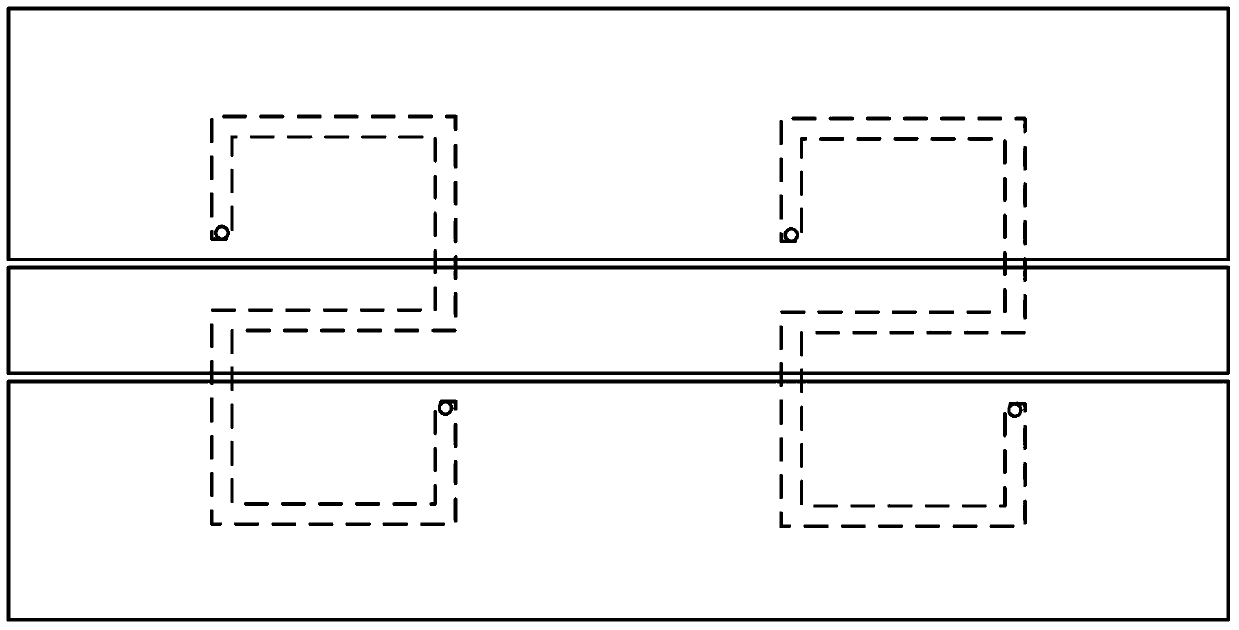
[0020] The present invention provides a coplanar waveguide bandstop filter based on a novel split resonant ring structure, such as figure 1 and figure 2 shown, including dielectric substrates. A central conduction band is arranged in the middle of the upper surface of the dielectric substrate, and the two ends of the central conduction band respectively extend to the edges of a pair of opposite sides of the dielectric substrate, and the central conduction band is perpendicular to the pair of opposite sides of the aforementioned dielectric substrate; Metal ground plates are also provided on both sides of the belt. The lower surface of the dielectric substrate is provided with at least one centrosymmetric split resonant ring structure, such as image 3 As shown, the split resonant ring structure includes the first to the seventh metal strips conn...


PUM


Abstract

The invention discloses a coplanar waveguide band-stop filter based on a novel split resonant ring structure, which includes a dielectric substrate, a central conduction band, metal grounding plates on both sides of the central conduction band, at least one split resonant ring structure, and a connecting split resonator Metal vias between the ring and the metal ground plate. Among them, the split resonant ring structure is used to generate a stop band, and the metal via is used to deepen the stop band and improve out-of-band frequency selectivity. Based on the traditional split resonant ring, the invention improves the structure of the split resonant ring, further reduces the electrical size, and has better out-of-band characteristics.

Description

technical field [0001] The invention relates to a coplanar waveguide band-stop filter based on a novel split resonant ring structure, which belongs to the field of microwave technology. Background technique [0002] Since the concept of the split resonant ring structure was proposed in 1999, the structure has attracted the interest of many researchers due to its excellent resonance performance. Traditional split resonators are widely used in microwave planar circuits. In microwave filters, by introducing a split resonant ring structure and adjusting the physical size of the structure, different operating frequencies can be obtained, which are usually used to suppress high-order harmonics, and have achieved good results. On the other hand, the split resonant ring structure can easily realize the miniaturization of the circuit because it can generate stronger resonance in a smaller structure. [0003] In the coplanar waveguide circuit, if the split resonant ring is placed di...

Claims


Application Information

Patent Timeline
Patent Type & Authority Patents(China)
IPC IPC(8): H01P1/20H01P1/212
Inventor 许锋濮菁菁
Owner NANJING UNIV OF POSTS & TELECOMM
Learn More