Charge control circuit and laser instrument provided with same

A charging control and circuit technology, applied in battery circuit devices, current collectors, circuit devices, etc., can solve problems such as user inconvenience, detection, and the inability of rechargeable battery BT to be fully charged, so as to improve the drive module, prolong the cycle life, and extend the The effect of the service life

Inactive Publication Date: 2015-09-30
CHANGZHOU HUADA KEJIE OPTO ELECTRO INSTR
View PDF4 Cites 0 Cited by
  • Summary
  • Abstract
  • Description
  • Claims
  • Application Information

AI Technical Summary

Problems solved by technology

However, when the instrument is turned on and working, because the rechargeable battery BT is in parallel with the load circuit, the charging control module cannot make a correct detection of the cut-off voltage BAT+ of the rechargeable battery BT, resulting in the failure of the rechargeable battery BT to be fully charged.
This defect has a certain impact on the cycle life of the rechargeable battery BT. At the same time, due to the insufficient capacity of the rechargeable battery BT, the working time of the laser instrument is shortened, which brings inconvenience to the user.

Method used


Image

  • Charge control circuit and laser instrument provided with same
  • Charge control circuit and laser instrument provided with same
  • Charge control circuit and laser instrument provided with same

Examples


Embodiment Construction

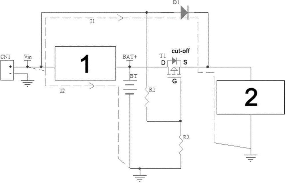
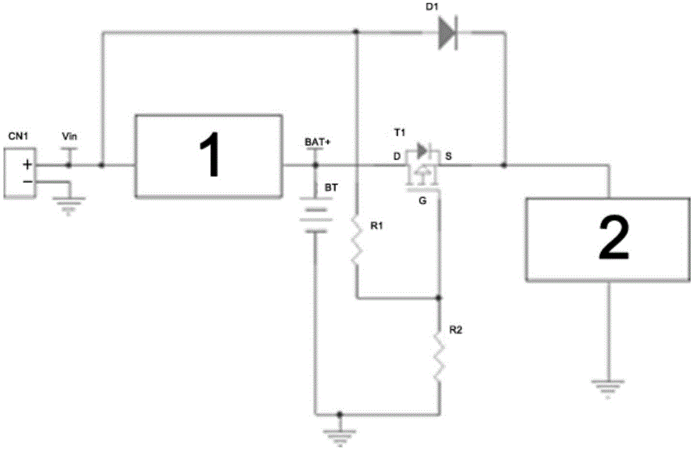
[0022] The advantages of the present invention will be further elaborated below in conjunction with the accompanying drawings and specific embodiments.

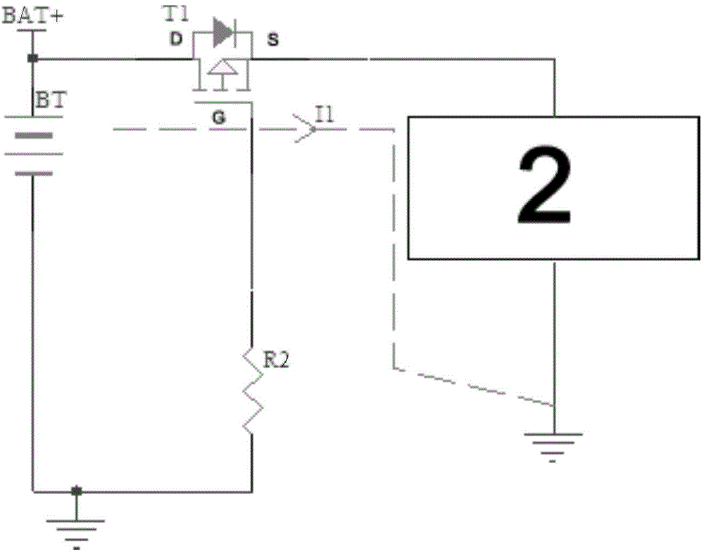
[0023] like figure 1 Shown is a circuit diagram of a charging control circuit in accordance with a preferred embodiment of the present invention, including an input source Vin, a charging management chip 1, a rechargeable battery BT and a load circuit 2; the first end of the charging management chip 1 and the input source Vin The positive pole is connected, and the second end is connected to the positive pole of the rechargeable battery BT and the first end of the load circuit 2; the negative pole of the rechargeable battery BT and the second end of the load circuit 2 are grounded, and also includes a diode D1 and a P-type MOS tube T1, resistor R1 and resistor R2; the positive pole of the diode D1 is connected to the positive pole of the input source Vin, and the negative pole is connected to the first end of the load circuit...


PUM

PropertyMeasurementUnit
Resistanceaaaaaaaaaa

Abstract

The invention provides a charge control circuit which comprises an input source, a charge management chip, a rechargeable battery and a load circuit, wherein a first end of the charge management chip is connected with a positive pole of the input source, a second end of the charge management chip is connected with a positive pole of the rechargeable battery and a first end of the load circuit, and a negative pole of the rechargeable battery and a second end of the load circuit are grounded; the charge control circuit also comprises a diode, a P-type MOS (Metal Oxide Semiconductor) transistor, a resistor R1 and a resistor R2; a positive pole of the diode is connected with that of the input source, a negative pole of the diode is connected with the first end of the load circuit, aand the P-type MOS transistor is connected between the second end of the charge management chip and the first end of the load circuit; a drain electrode D is connected with a second end of the charge management chip, a source electrode S is connected with the first end of the load circuit, a grid electrode G is connected with the positive pole of the input source by virtue of the resistor R1, and the grid electrode G and the negative pole of the rechargeable battery are grounded in parallel by virtue of the resistor R2. The invention also discloses a laser instrument provided with the charge control circuit.

Description

technical field [0001] The invention relates to a charging circuit, in particular to a charging control circuit capable of controlling battery charging. [0002] The invention also relates to a laser instrument with a charging control circuit. Background technique [0003] The charging management circuit in the prior art is only suitable for effectively charging the rechargeable battery BT when the instrument is turned off. However, when the instrument is turned on, because the rechargeable battery BT is connected in parallel with the load circuit, the charging control module cannot make correct detection of the cut-off voltage BAT+ of the rechargeable battery BT, resulting in the failure of the rechargeable battery BT to be fully charged. This defect has a certain impact on the cycle life of the rechargeable battery BT. At the same time, due to the insufficient capacity of the rechargeable battery BT, the working time of the laser instrument is shortened, which brings inco...

Claims


Application Information

Patent Timeline
IPC IPC(8): H02J7/00
Inventor 张瓯牛青王建勇
Owner CHANGZHOU HUADA KEJIE OPTO ELECTRO INSTR
Why Eureka
Try Eureka