
Eureka
For R&D, Eureka makes reading and utilizing patents & technical documents easy.
Eureka AIR
Designed for self-driven R&D workflows. Generate viable solutions, solve complex R&D challenges, empower your innovation with AI.

Eureka Materials
Designed for material experts only. Revolutionize your material R&D, from search, analyze, to developing new materials.

TechResearch
Generate reliable direction feasibility study reports for your R&D in just a few steps.

TechSeek
Discover and master advanced knowledge NOW. Basics, ideas, possibilities, all at once.

TechMind
As an expert in R&D Theories, TechMind can generates customized viable solutions instantly.

TechRisk
Analyze your overall solution with one click, know your potential R&D risks in advance.

TechMonitor
Get weekly tech updates, stay abreast of the latest tech innovations and key insights.
Mobile electronic product and metal middle frame thereof
A technology of product metal and mobile electronics, applied in the direction of rack/frame structure, etc., can solve the problems of high welding cost, separation of outer frame and middle plate, unfavorable production of enterprises, etc., and achieve the effect of high connection strength and firm connection
- Summary
- Abstract
- Description
- Claims
- Application Information
AI Technical Summary
Problems solved by technology
Method used
Image

Examples
specific Embodiment approach 1
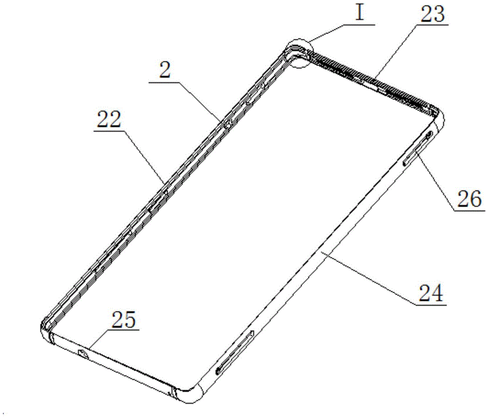
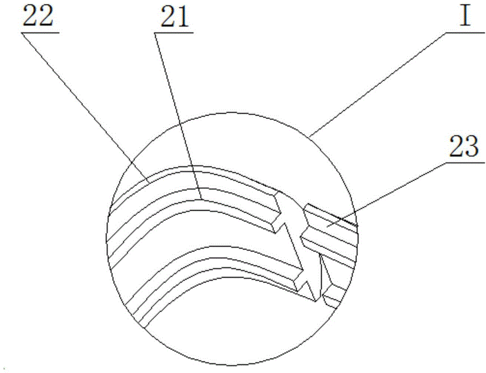
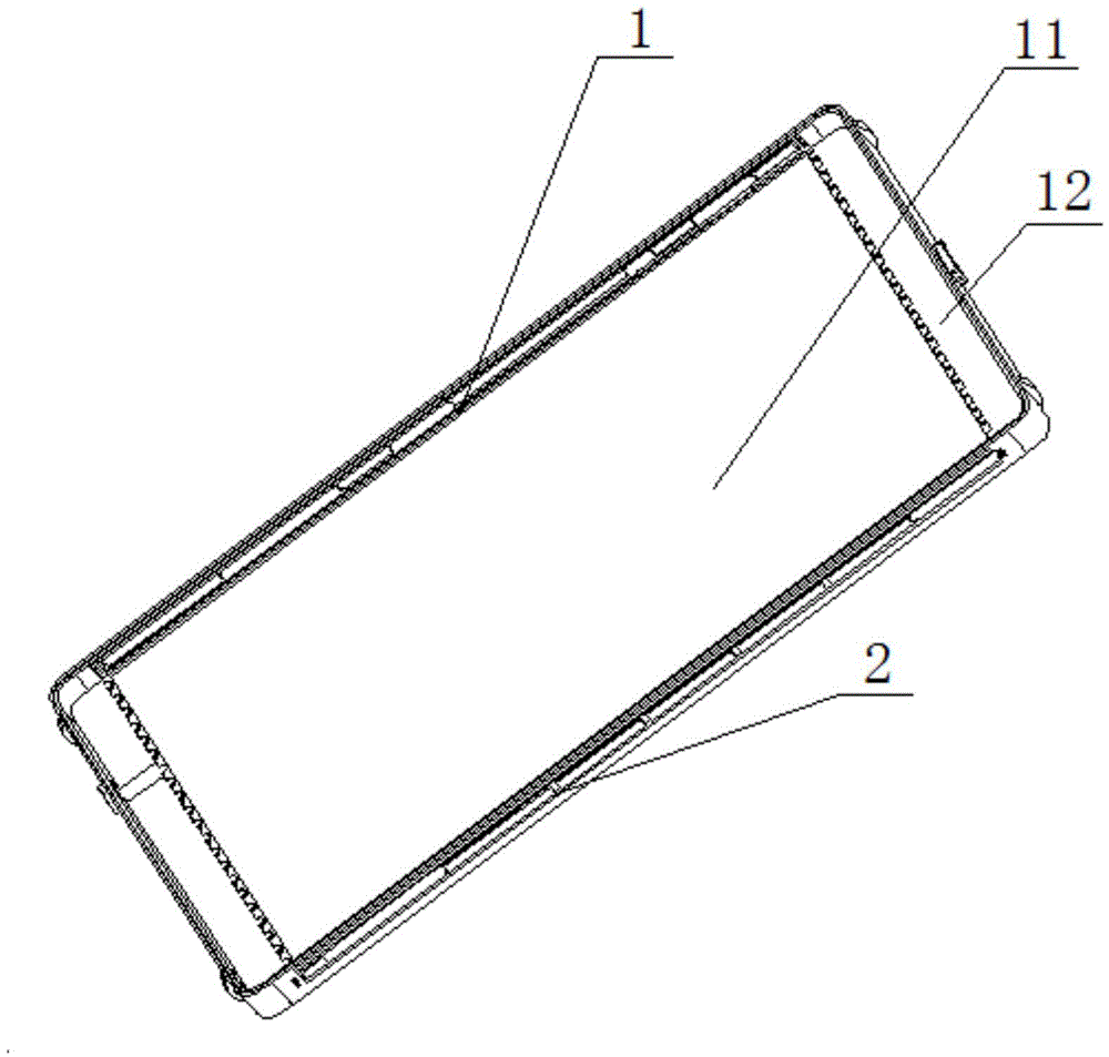
[0033] Please combine Figure 1-5 , figure 1 It is a structural schematic diagram of the outer frame of the metal middle frame of the mobile electronic product provided by the present invention; figure 2 Yes figure 1 Partial enlarged view of I; image 3 It is a structural schematic diagram of the metal middle frame of the mobile electronic product provided by the present invention; Figure 4 It is a partial cross-sectional view of the specific embodiment of the present invention-providing the outer frame; Figure 5 It is a partial cross-sectional view of a metal middle frame of a mobile electronic product provided in Embodiment 1 of the present invention.
[0034] The invention provides a metal middle frame of a mobile electronic product, the middle frame has high strength, and parts will not be separated due to violent impact. The metal middle frame includes a middle plate 1 and an outer frame 2, the middle plate 1 and the outer frame 2 are made of metal, the middle pla...
specific Embodiment approach 2
[0041] The differences between this embodiment and the specific embodiment one are:
[0042]The strip-shaped protrusions 21 on the inner wall of the outer frame 2 are arranged symmetrically along the center line of the inner wall, so the width of the strip-shaped protrusions in this embodiment may be smaller than the width of the strip-shaped protrusions 21 in the first embodiment. The width can also be the same as that in the first embodiment, but its overall width cannot exceed the width of the outer frame 1 . More specifically, in order to make the adhesion between the plastic frame 12 and the outer frame 2 more firm, plastic matching grooves 123 are evenly distributed on both sides of the first glue storage groove 121 to cooperate with the strip-shaped protrusions 21 .
[0043] Please refer to Figure 6-7 , Image 6 It is a partial cross-sectional view of the outer frame provided in Embodiment 2 of the present invention; Figure 7 It is a partial cross-sectional view of...
specific Embodiment approach 3
[0046] This implementation mode differs from the specific implementation modes 1 and 2 in that:
[0047] Please combine Figure 8-9 , Figure 8 It is a partial cross-sectional view of the outer frame provided in the third embodiment of the present invention; Figure 9 It is a partial cross-sectional view of a metal middle frame of a mobile electronic product provided in Embodiment 3 of the present invention.
[0048] The strip-shaped protrusions 21 are located at both ends of the inner wall of the outer frame 2, and the outer frame 2 has a "[" structure, and the side of the plastic frame 12 in contact with the inner wall of the outer frame 2 is provided with a first protrusion 124, and the The first protrusion 124 is in contact with the sidewall of the outer frame 2 , and the first glue storage tank 121 is disposed on the first protrusion 124 .
[0049] The rest of the structures in this embodiment are the same as those in Embodiments 1 and 2, so details will not be repeate...
PUM
 Abstract
Description
Claims
Application Information
 - R&D Engineer
- R&D Manager
- IP Professional
- Industry Leading Data Capabilities
- Powerful AI technology
- Patent DNA Extraction
Browse by: Latest US Patents, China's latest patents, Technical Efficacy Thesaurus, Application Domain, Technology Topic, Popular Technical Reports.
© 2024 PatSnap. All rights reserved.Legal|Privacy policy|Modern Slavery Act Transparency Statement|Sitemap|About US| Contact US: help@patsnap.com