Eureka AIR delivers breakthrough ideas for toughest innovation challenges, trusted by R&D personnel around the world.

Method for simulating thoracic 4DCT

A 4D, chest technology, applied in the field of 4D computed tomography, can solve the problem that the tumor location cannot be determined in situ

Inactive Publication Date: 2015-09-30
MITSUBISHI ELECTRIC CORP
View PDF2 Cites 14 Cited by
  • Summary
  • Abstract
  • Description
  • Claims
  • Application Information

AI Technical Summary

Problems solved by technology

Moreover, 4DCT acquisition alone cannot determine tumor location in situ

Method used


Image

  • Method for simulating thoracic 4DCT
  • Method for simulating thoracic 4DCT
  • Method for simulating thoracic 4DCT

Examples


Embodiment Construction

[0025] Chest 4DCT Simulator Method

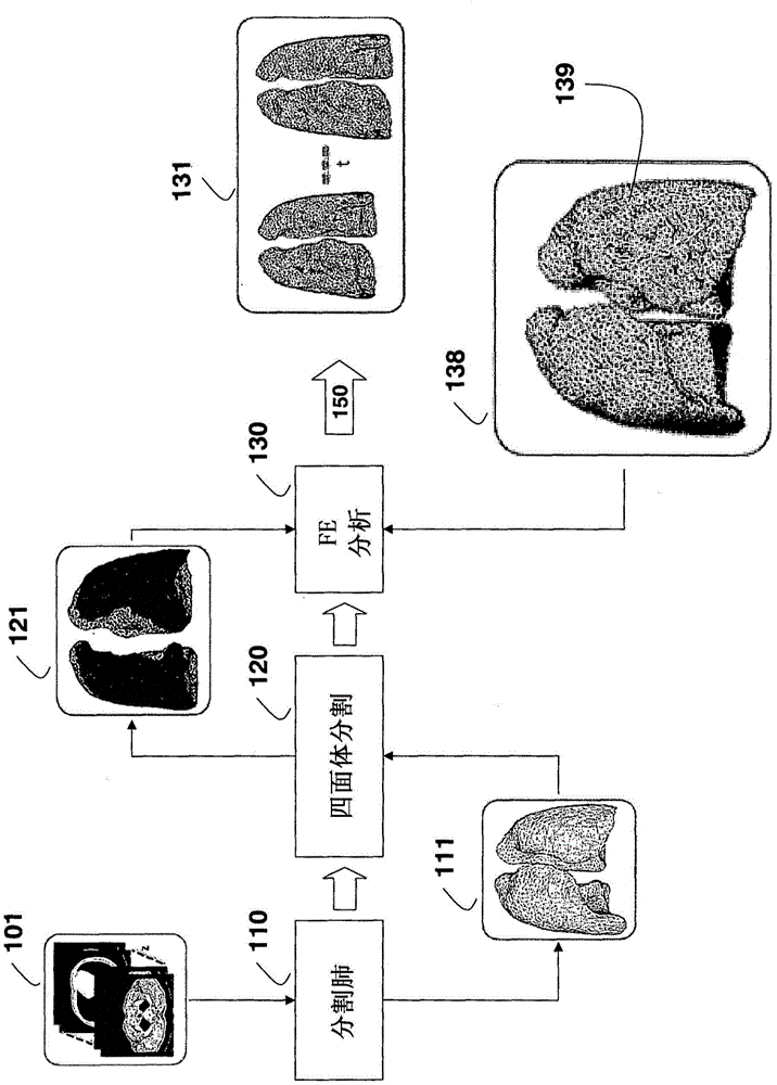
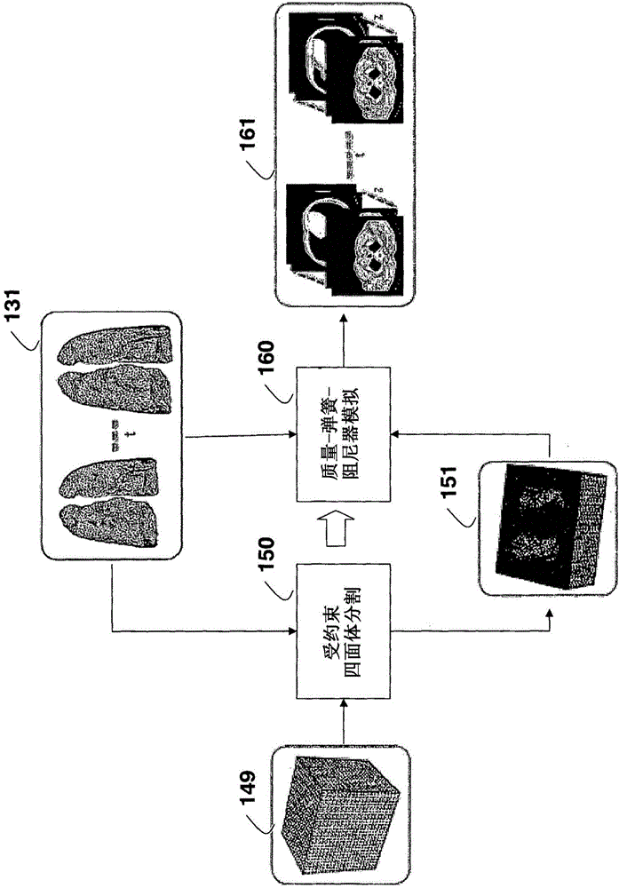
[0026] figure 1 and figure 2 A processing pipeline of a chest four-dimensional computed tomography (4DCT) simulator method according to an embodiment of the invention is shown. The method includes lung deformation and 4DCT scan simulation. The method can be performed in a processor coupled to memory and input / output interfaces known in the art. It should be understood that the present invention may also be used to simulate other types of tissue or organ deformations, and utilize other types of medical scans known in the art.

[0027] The input to the method is a single chest CT scan 101 . The CT scan is segmented 110 to generate a surface mesh 111 of the lungs. A tetrahedral partitioning 120 is applied to the surface mesh to obtain a first volumetric mesh 121 .

[0028] Using boundary constraints and load definitions 138 , a finite element (FE) analysis 130 is applied to the first volume mesh to obtain lung deformations 131 . Lung d...


PUM


Abstract

Four-dimensional (4D) computed tomography (CT) is simulated by first generating a surface mesh from a single thoracic CT scan. Tetrahedralization is applied to the surface mesh to obtain a first volume mesh. Finite element analysis, using boundary constraints and load definitions, is applied to the first volume mesh to obtain a lung deformation according to an Ogden model. Constrained tetrahedralization, using control points, is applied to the lung deformation to obtain a second volume mesh, which is then deformed using mass-spring-damper simulation to produces the 4DCT.

Description

technical field [0001] The present invention relates generally to four-dimensional computed tomography (4DCT) and, more particularly, to simulating breathing for radiation therapy planning. Background technique [0002] The use of four-dimensional computed tomography (4DCT) is common practice for radiation therapy planning in the thoracic region. Information from 4DCT allows radiation oncologists to plan accurate treatment for moving tumors, deliver radiation at predetermined intervals during the respiratory cycle, and reduce the risk of treatment-related side effects. [0003] Approaches for 4DCT include retrospective slice classification, and prospective sinogram selection. For retrospective slice classification methods, projection data are acquired continuously over time intervals longer than the respiratory cycle. Multiple slices corresponding to different times are reconstructed and sorted into respiratory phase bins using various respiratory signals. For the prospec...

Claims


Application Information

Patent Timeline
Patent Type & Authority Applications(China)
IPC IPC(8): G06T17/20A61N5/10
CPCG06T17/20G06F19/3437A61N5/1037G06T2200/08G06T2210/41G16H50/50G16Z99/00
Inventor F·波里克里李冯
Owner MITSUBISHI ELECTRIC CORP
Why Eureka
Eureka Blog
Learn More