Piezoelectric inducing implant denture

A piezoelectric sensing and denture technology, applied in implantology, medical science, dentistry, etc., can solve the problems of shortened implant life, inability to complete protection actions, and no functional products, etc., to achieve the effect of self-detection and protection

Inactive Publication Date: 2015-10-07
SHANGHAI EAST HOSPITAL
View PDF6 Cites 8 Cited by
  • Summary
  • Abstract
  • Description
  • Claims
  • Application Information

AI Technical Summary

Problems solved by technology

[0003] The biggest difference between dental implants and natural teeth is that dental implants lack periodontal ligament. There are a large number of neurovascular lymphoepithelial cells and positioning receptors in the periodontal ligament, which can keenly sense the force of the teeth. However, when the patient loses natural teeth , the periodontal ligament is subsequently lost and atrophied, which results in the lack of sharp and direct pain and pressure sensation on the implant, and some excessive force of the patient, such as vigorous chewing and occlusal damage to the implant, periodontal and crown Unable to detect and prevent in advance, resulting in bone trauma around the implant, fracture of the components of the implant, local stress concentration of the crown, and cracks in the outlet line, which eventually lead to shortened life of the patient's implant and shedding
Therefore, regular inspection of implants after implantation has become a clinically necessary work and task, but it is often found late and cannot be rescued.
[0004] Since the 1990s, foreign countries have been trying various nerve restoration and repair techniques in this field, but the progress has been slow. For example, PECK proposed that there is a bone sensor around the implant. WADA et al. once found that there are 200 micron nerve filaments in the implant. existence, but only
[0005] Therefore, the existing implant technology cannot complete self-sensing and feedback pain signals to the central nervous system, and cannot complete the protective action, resulting in a short lifespan of the implant and no related functional products.

Method used


Image

  • Piezoelectric inducing implant denture
  • Piezoelectric inducing implant denture

Examples


Embodiment Construction

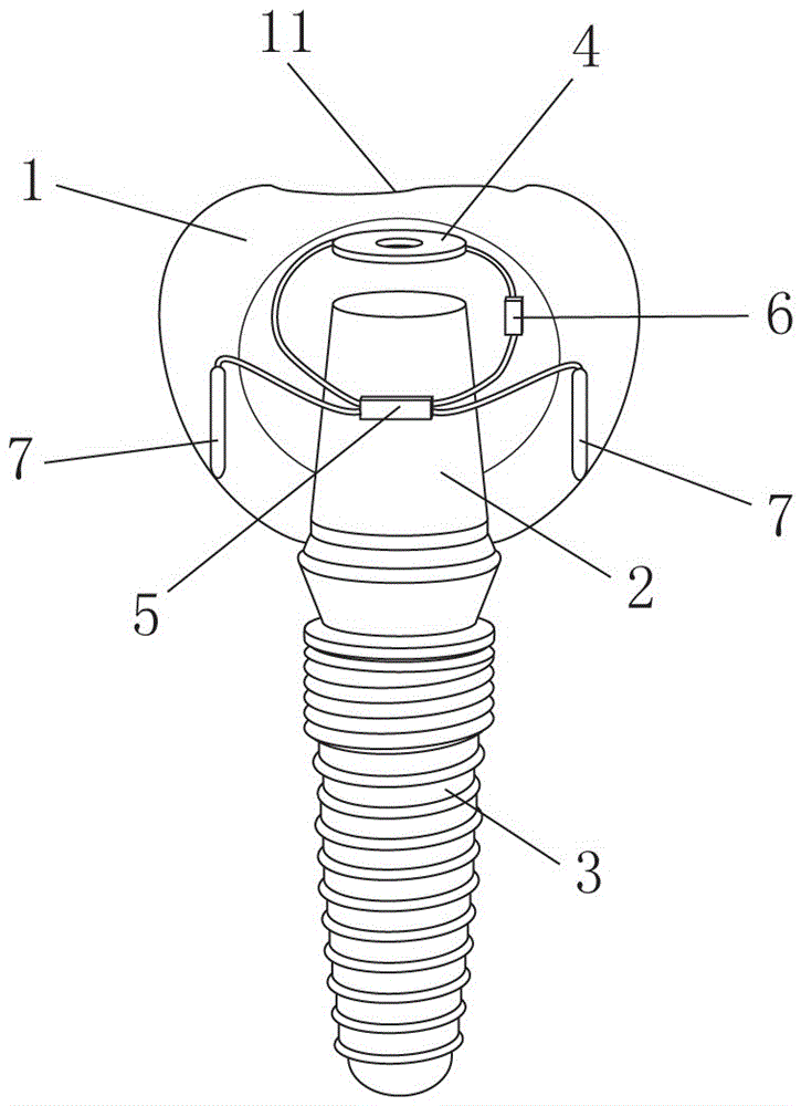
[0014] according to figure 1 , figure 2 , the present invention includes a crown 1, an abutment 2, and an implant 3. The top surface of the crown 1 is an occlusal force bearing surface 11 of the occlusal force, and an alveolar nerve stimulation device is arranged inside the crown 1. The alveolar nerve stimulation device converts the occlusal force received by the occlusal force surface 11 into electrical energy, and then releases the current to stimulate the alveolar nerve.

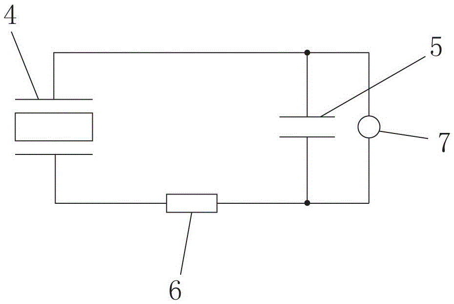
[0015] The alveolar nerve stimulation device includes an annular piezoelectric ceramic sheet 4, a chip capacitor 5, a chip resistor 6, and a discharge electrode 7, and the piezoelectric ceramic sheet 4, chip capacitor 5, and chip resistor 6 are connected in series in sequence, so that The discharge electrodes 7 are connected in parallel at both ends of the chip capacitor 5; the piezoelectric ceramic sheet 4 is fixed directly below the occlusal force-bearing surface 11 of the dental crown, and the top su...


PUM


Abstract

The invention discloses a piezoelectric inducing implant denture, which comprises a dental crown, an abutment and an implant, wherein the top surface of the dental crown is an occlusive thrust face for interlocking force. The piezoelectric inducing implant denture is characterized in that an alveolar nerve stimulating device is arranged in the dental crown; the interlocking force on the occlusive thrust face is converted into electric energy by the alveolar nerve stimulating device; and then current is released to simulate alveolar nerves. According to the piezoelectric inducing implant denture, mechanical energy that a patient excessively utilizes the denture is converted into electric energy; a discharge electrode is released to peripheral alveolar nerves to stimulate nervous centralis of a human brain and prompt the patients to timely take protective measures, so that parodontium neurotransmission is replaced; the targets of self-detection and protection of the denture are realized; and the blank in the field is filled up.

Description

technical field [0001] The invention relates to an implant denture, in particular discloses a piezoelectric induction implant denture. Background technique [0002] In the clinical work of stomatology, dental caries and periodontitis lead to the loss and loss of patients' teeth. In order to restore the function of the teeth, the relatively new clinical restoration technology in the past uses implant dentures. Generally, implant dentures include crowns, abutments and The implant screw consists of three parts. The implant screw is implanted in the alveolar bone, and the abutment acts as a connector to connect the crown and the screw, and acts as a framework to support the entire crown. [0003] The biggest difference between dental implants and natural teeth is that dental implants lack periodontal ligament. There are a large number of neurovascular lymphoepithelial cells and positioning receptors in the periodontal ligament, which can keenly sense the force of the teeth. Howe...

Claims


Application Information

Patent Timeline
Patent Type & Authority Applications(China)
IPC IPC(8): A61C8/00
Inventor 谭鸾君徐国权王磊
Owner SHANGHAI EAST HOSPITAL
Why Eureka
Try Eureka