Repair method of cylinder body

A cylinder block and plunger technology, which is used in the field of repairing the defects of the cylinder block, can solve problems such as rotten threads of threaded holes and scrapped parts, and achieves the effect of ensuring installation quality and avoiding economic losses.

Inactive Publication Date: 2015-10-07
LIUZHOU BAITIAN MACHINERY
View PDF4 Cites 9 Cited by
  • Summary
  • Abstract
  • Description
  • Claims
  • Application Information

AI Technical Summary

Problems solved by technology

However, this repair method can only repair some cracks, and some large defects can be repaired by welding; figure 1 As shown in the threaded hole of a mounting stud in the cylinder, the operator mistakenly drilled the threaded hole at the center position b at the center position a. After a period of time, the threaded holes are prone to rotten teeth, which will lead to the scrapping of parts

Method used


Image

  • Repair method of cylinder body
  • Repair method of cylinder body

Examples


Embodiment 1

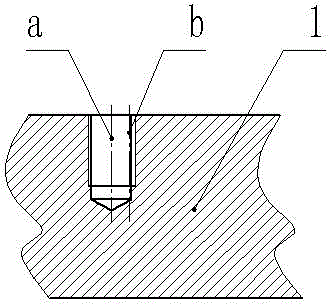
[0017] Such as figure 1 The shown cylinder includes a step 1 with a threaded hole on the centerline a, the threaded hole on the centerline a is a threaded hole drilled incorrectly, and the correct position is that the centerline of the threaded hole should be the centerline b.

[0018] The repair method of the cylinder includes the following steps:

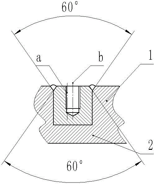
[0019] A. Process a counterbore at the threaded hole of step 1. The inner diameter of the counterbore is 2.5 times the diameter of the threaded hole, and the depth of the counterbore is 1.2 times the depth of the threaded hole. Chamfer;

[0020] B. A car plunger 2, the outer circle of the plunger 2 is a clearance fit with the counterbore, the height of the plunger is equal to the depth of the counterbore, and the plunger 2 is provided with an inner chamfer of 5×60° at one end; the plunger The material of 2 is the same as that of the cylinder block, both of which are iron castings;

[0021] C. Use a mallet to knock the plunger ...

Embodiment 2

[0026] Such as figure 1 The shown cylinder includes a step 1 with a threaded hole on the centerline a, the threaded hole on the centerline a is a threaded hole drilled incorrectly, and the correct position is that the centerline of the threaded hole should be the centerline b.

[0027] The repair method of the cylinder includes the following steps:,

[0028] A. Process a counterbore at the threaded hole of step 1. The inner diameter of the counterbore is 3 times the diameter of the threaded hole, and the depth of the counterbore is 1.5 times the depth of the threaded hole. Chamfer;

[0029] B. A car plunger 2, the outer circle of the plunger 2 is a clearance fit with the counterbore, the height of the plunger is equal to the depth of the counterbore, and the plunger 2 is provided with an inner chamfer of 5×60° at one end; the plunger The material of 2 is the same as that of the cylinder block, both of which are iron castings;

[0030] C. Use a mallet to knock the plunger 2...


PUM


Abstract

The invention discloses a repair method of a cylinder body. The repair method comprises following steps: A, adopting polystyrene to produce an internal lost foam casting mould and an external lost foam casting mould of a load-reducing valve body in the same shape of the load-reducing valve body for standby-by application; B, filling dry sand into the interior of the internal lost foam casting mould and carrying out vibration ramming operation and vacuum pumping operation from a reserved opening thereof, adopting resin-bonded sand to seal the reserved opening of the internal lost foam casting mould such that a reinforcing block is formed by the internal lost foam casting mould; C, combining the internal lost foam casting mould formed with the reinforcing block to the external lost foam casting mould of the load-reducing valve body in order to form an overall mould of the load-reducing valve body; D, disposing the overall mould of the load-reducing valve body into a sand box (3); filling dry sand into the sand box (3), carrying out vibration ramming operation and vacuumizing the interior of the sand box (3); E, casting the sand box (3) from a pouring channel so that lost foam casting of the load-reducing valve body is finished. Compared with the prior art, the repair method of the cylinder body helps to solve problems including poor casting quality of the load-reducing valve body and high cost.

Description

technical field [0001] The invention relates to the technical field of casting repair welding, in particular to a method for repairing defects of a cylinder body. Background technique [0002] The cylinder block is a cast iron casting. The main working area of ​​the cylinder block is the cylinder hole in the center of the cylinder block. During the use of the cylinder block, there will be some defects that do not affect the work of the cylinder block and the cylinder hole. Usually, the repair glue is used to repair the defects. Use after repairing to reduce the scrap rate of defective products. However, this repair method can only repair some cracks, and some large defects can be repaired by welding; figure 1 In the threaded hole of a mounting stud of the cylinder block shown, the operator mistakenly drilled the threaded hole with the center at b at the center position at a. If welding repair is performed, the threaded hole should be drilled again. After a period of time, ...

Claims


Application Information

Patent Timeline
Patent Type & Authority Applications(China)
IPC IPC(8): B23P6/02B23K31/02
CPCB23K31/02B23P6/02
Inventor 谭皓原谭科文
Owner LIUZHOU BAITIAN MACHINERY
Why Eureka
Try Eureka