A Device for Adjusting the Axial Angle of an End Beam Traveling Wheel

A technology for adjusting devices and wheels, applied in the directions of transportation, packaging, loading/unloading, etc., can solve the problems of end beam wheel deviation, difficult adjustment, long cycle, etc., to achieve the effect of controlling quality, reducing welding workload, and increasing strength

Active Publication Date: 2017-03-01
NORTHERN HEAVY IND GRP CO LTD
View PDF5 Cites 0 Cited by
  • Summary
  • Abstract
  • Description
  • Claims
  • Application Information

AI Technical Summary

Problems solved by technology

[0003] So far, in most bulk material circular stockyards, in order to ensure along the circular track A (see Figure 5 ) center running smoothly, the support in the traveling end beam, the end beam body and the trolley must form a certain angle to ensure that the wheel axis points to the center B of the stockyard (see Figure 5 ), but the manufacturing accuracy of this large-scale steel structure can only approximately meet the required angle during welding, and the on-site installation is affected by errors in civil engineering and on-site measurement, making it difficult for the centerline of the wheel and the track surface to meet the drawings. Requirements, during the test run, it often happens that the end beam wheel deviates from the center of the circular track A during the running process and falls off the track. At present, in most cases, only the middle support and end beam body of the end beam can be readjusted The support and the end beam body are welded together, and the two pieces need to be disassembled during field adjustment) and the angle between the trolley, or by adjusting the anchor bolts that have been grouted in the civil foundation before the installation of the equipment to fix the track The method of adjusting the track, the above two processing methods lead to each adjustment is difficult and the cycle is long

Method used


Image

  • A Device for Adjusting the Axial Angle of an End Beam Traveling Wheel
  • A Device for Adjusting the Axial Angle of an End Beam Traveling Wheel
  • A Device for Adjusting the Axial Angle of an End Beam Traveling Wheel

Examples


Embodiment Construction

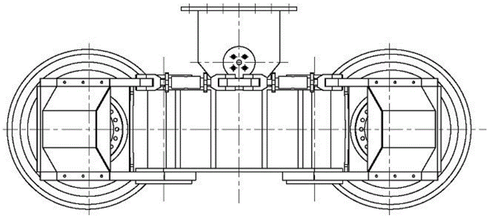
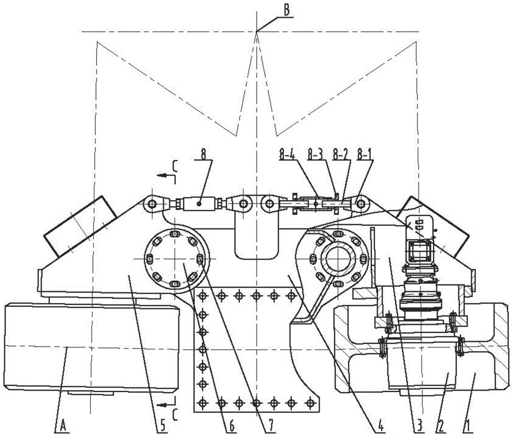
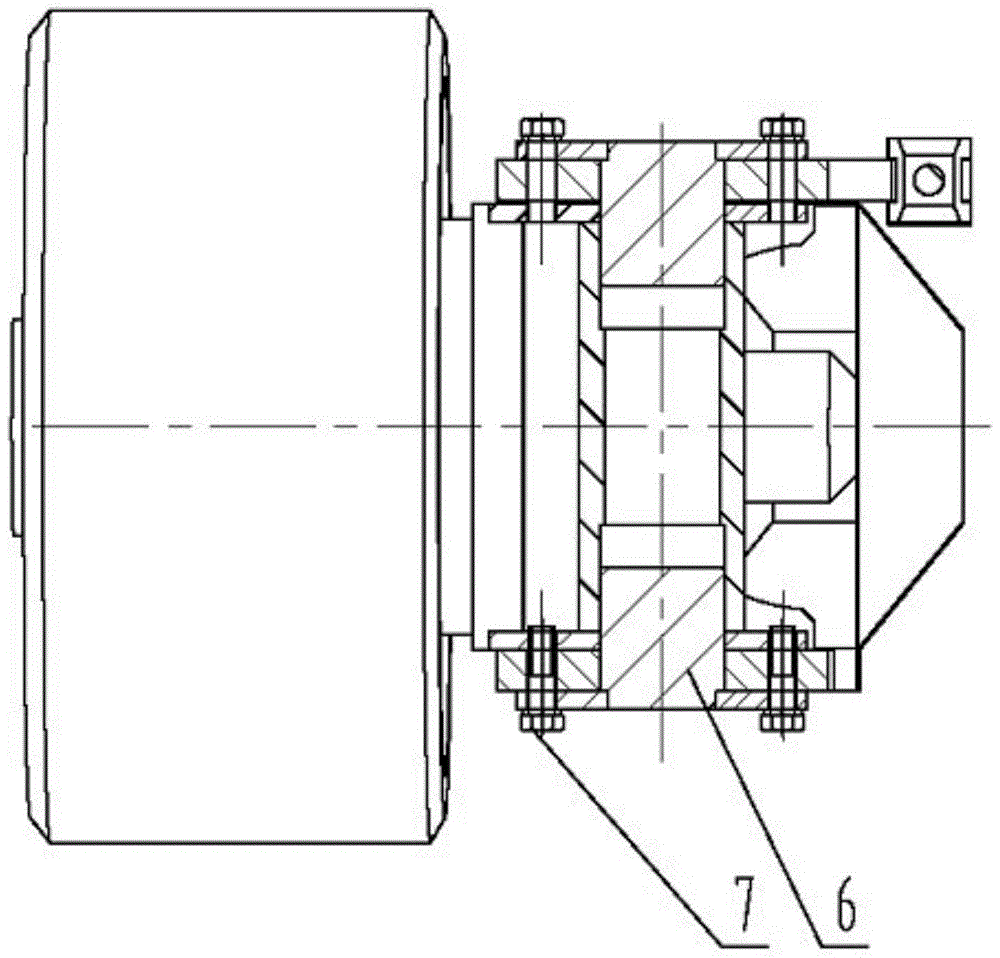
[0018] Referring to the accompanying drawings, a device for adjusting the axial angle of an end beam traveling wheel includes a wheel 1, a drive unit 2, a left wheel frame 3, a trolley frame 4, a right wheel frame 5, a pin shaft 6, a connecting bolt 7, and an adjustment device Combination 8, the trolley frame 4 is connected with the left wheel frame 3 and the right wheel frame 5 using hinge shafts, and the trolley frame 4 and the left wheel frame 3 and the right wheel frame 5 pass through the pin shaft 6 at the hinge point with connecting bolts 7 connection, the wheel 1 is installed on the drive unit 2 and connected with the left wheel frame 3 and the right wheel frame 5, two sets of wheels 1 and two sets of drive units 2 are respectively connected with the left wheel frame 3 and the right wheel frame 5, and the left wheel frame 3 1. The right wheel frame 5 is connected with the trolley frame 4 through the hinge shaft 6 and the connecting bolt 7, one side of the adjustment devi...


PUM


Abstract

The invention discloses an axial angle adjusting device of an end beam walking wheel, which is applied to circular storage homogenization stockyards in such fields as papermaking, water conservancy, metallurgy, electric power, port docks, coals, building materials and chemical engineering. The device comprises wheels, driving units, a left wheel frame, a bogie frame, a right wheel frame, pin shafts, connecting bolts and an adjusting device combination, wherein the bogie frame is connected with the left wheel frame and the right wheel frame by hinge shafts; the bogie frame is connected with the left wheel frame and the right wheel frame through the pin shafts in the hinged points by the connecting bolts; the wheels are mounted on the driving units, and are connected with the left wheel frame and the right wheel frame; the two sets of wheels and the two sets of driving units are respectively connected with the left wheel frame and the right wheel frame; and one side of the adjusting device combination is connected with the left wheel frame and the right wheel frame. The device is convenient to operate, so that the scene installation and debugging period is largely shortened; an end beam body is wholly welded in a factory, so that the strength is enhanced, and the scene welding workload is reduced; and the structural part quality is controlled.

Description

technical field [0001] The invention relates to an adjusting device for adjusting the axial angle of the end beam traveling wheel in the fields of papermaking, water conservancy, metallurgy, electric power, port, coal, building materials, chemical industry and the like, which can accurately adjust the circular stock yard. Background technique [0002] At present, the circular stockyard stacker and reclaimer is a kind of stacking and reclaiming equipment that is used in the stockyard as a whole. Stackers and reclaimers. The reclaimer is mainly composed of main beam, reclaiming system and end beam. One end of the main girder is hinged on the external turntable under the center column, and the main girder turns around the center column through the turntable; the other end of the main girder is connected to the traveling end beam, and the traveling end beam is equipped with a traveling drive device, and the traveling wheel axle is installed into the walking In the drive gear r...

Claims


Application Information

Patent Timeline
Patent Type & Authority Patents(China)
IPC IPC(8): B65G65/02
CPCB65G65/02
Inventor 杜海滨费勇任志刚张亮王新雷范磊冯学慧卢士先康硕吴井辉金铁岩尚飞王辉崔安
Owner NORTHERN HEAVY IND GRP CO LTD
Why Eureka
Try Eureka