Urban surface runoff filtration system

A surface runoff and urban technology, applied in the direction of water/sewage multi-stage treatment, adsorption water/sewage treatment, water/sludge/sewage treatment, etc., to achieve efficient removal effect

Inactive Publication Date: 2015-10-07
CHINA UNIV OF GEOSCIENCES (WUHAN)
8 Cites 4 Cited by

AI-Extracted Technical Summary

Problems solved by technology

[0005] Aiming at the problems existing in the prior art, the embodiment of the present invention provides an urban surface runoff filtration system, which is used to solve the problem tha...

Method used

Wherein, described emptying pipe 9 is arranged on described gravel grid layer 6, is connected with described drainage chamber 3, is...

Abstract

The invention provides an urban surface runoff filtration system. The system comprises: a deposition chamber used for removing large-granule pollutants in surface runoff through deposition; a filtration chamber used for removing small-granule pollutants in the surface runoff through filtering adsorption of the surface runoff; and a water drainage chamber used for draining the filtered surface runoff through a water drainage pipe. The filtration system is applied in land space-limited urban roads and parking lots in a buried form, can efficiently remove pollutant granules in the surface runoff without influencing the surface functions, allows the removal rate of the pollutant granules to reach above 90%, and reduces the influences of the urban road and parking lot surface runoff pollution on the quality of receiving water.

Application Domain

Multistage water/sewage treatmentWater/sewage treatment by sorption

Technology Topic

Surface functionChemistry +13

Image

  • Urban surface runoff filtration system
  • Urban surface runoff filtration system

Examples

  • Experimental program(1)

Example Embodiment

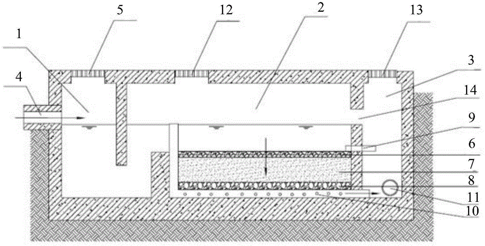
[0023] In order to effectively remove particulate pollutants in surface runoff and reduce urban surface runoff pollution without affecting the normal functions of the surface, the present invention provides an urban surface runoff filtration system. The system includes: a sedimentation chamber. The chamber is used to remove large particle pollutants in the surface runoff through precipitation; the filter chamber is used to filter and adsorb the surface runoff to remove small particle pollutants in the surface runoff; the drainage chamber, the The drainage chamber is used to discharge the filtered surface runoff through the drainage pipe.
[0024] The technical solution of the present invention will be further described in detail below through the drawings and specific embodiments.
[0025] This embodiment provides an urban surface runoff filtration system, such as figure 1 As shown, the system includes: a precipitation chamber 1, a filter chamber 2, a drainage chamber 3; wherein,
[0026] The precipitation chamber 1 is used to remove large particles of pollutants in the surface runoff through precipitation; specifically, the system further includes: a water inlet pipe 4 and a first opening 5; wherein, the water inlet pipe 4 is arranged in the precipitation On one side of the chamber 1, the surface runoff can flow into the precipitation chamber 1 through the inlet pipe 4, and the precipitation chamber 1 precipitates large-particle pollutants in the surface runoff; the first opening 5 is provided At one end of the precipitation chamber 1, after the large-particle contaminants are deposited, the large-particle contaminants are cleaned through the first opening 5.
[0027] Here, the area of ​​the precipitation chamber 1 can be determined by formula (1);
[0028] A s = Q X 3600 q - - - ( 1 )
[0029] In formula (1), the A s Is the area of ​​the precipitation chamber 1, the Q is the preset flow rate of the surface runoff, the q is the hydraulic load, and the hydraulic load is the quotient of the water inflow and the area of ​​the precipitation chamber 1 per unit time Value, the value of q can be 1.5~3.0m 3 /m 2 ·H.
[0030] Further, the filter chamber 2 is used to filter and adsorb the surface runoff after precipitation to remove small particle pollutants in the surface runoff; specifically, the filter medium of the filter chamber 2 includes: a gravel grid Layer 6, coarse sand layer 7 and gravel drainage layer 8. Wherein, the 6 layers of the gravel grid are composed of gravel with a particle size of 1 to 2 cm and a thickness of 5 cm; the coarse sand layer 7 is composed of coarse sand with a particle size of 0.5 to 2 cm and a thickness of 45 to 60 cm; The gravel collection and drainage layer 8 is composed of gravel with a particle size of 2 to 4 cm and a thickness of 15 to 30 cm.
[0031] The area of ​​the filter chamber 2 can be determined by formula (2);
[0032] A f =V×d f /[k×(h f +d f )×t f ] (2)
[0033] In formula (2), the A f Is the area of ​​the filter chamber 2, the V is the preset total surface runoff, and the h f Is the water head, the water head is the depth of water on the surface of the filter medium, generally 1/2 of the depth of water on the surface of the filter medium, the d f Is the depth of the filter medium, which can be 0.45~0.6m, the t f It is a preset emptying time, generally no more than 3 days; the k is the hydraulic conductivity of the filter medium.
[0034] Here, if organic pollutants, heavy metals, phosphorus, etc. are to be removed from the surface runoff, an organic filter material and a filler with high phosphorus adsorption may be added to the filter chamber 2. The filler may include granular activated carbon and limestone.
[0035] The system also includes: an emptying pipe 9, an open-hole collection and drainage pipe 10, a drainage pipe 11, a second opening 12 and a third opening 13;
[0036] Wherein, the emptying pipe 9 is arranged on the gravel grid layer 6 and is connected to the drainage chamber 3 for emptying the surface runoff on the surface of the gravel grid layer 6 to facilitate maintenance of the broken stone grid layer 6 Stone grid layer 6.
[0037] The open-hole collection and drainage pipe 10 is arranged in the gravel collection and drainage layer 8 for discharging the filtered surface runoff to the drainage chamber 3, and the drainage chamber 3 is filtered through the drainage pipe 11 The surface runoff is discharged to the municipal rainwater pipe network. Here, the perforated drainage pipe 10 needs to be provided with a flushing pipe to facilitate flushing the sediment in the perforated drainage pipe 10.
[0038] The second opening 12 is provided at one end of the filter chamber 2, and the particulate contaminants in the filter chamber 2 can be cleaned through the second opening 13, and the third opening 13 is provided in the drainage chamber. At one end of 3, the pipeline in the drainage chamber 3 can be opened, closed, and repaired through the third opening 13.
[0039] In addition, the system is also provided with an overflow zone 14, which is set at the junction of the filter chamber 2 and the drainage chamber 3. In the case of heavy rainfall and large water volume, the surface The runoff can directly overflow into the drainage chamber 3, and the system can adopt online filtration treatment for the surface runoff.
[0040] In addition, the system can also take off-line filtration treatment on the surface runoff; specifically, for example, when rainfall occurs, the filtration system only needs to pass the inlet pipe 4 to intercept the heavily polluted surface runoff by 10-15 mm at the initial stage and filter it.
[0041] The surface runoff filtration system provided by the present invention can utilize the limited space around urban roads, parking lots, etc., without affecting the normal function of the surface, and efficiently remove pollutant particles in urban surface runoff, and the removal rate of particulate pollutants Up to 90%, reducing the impact of surface runoff pollution from urban roads and parking lots on the water quality of receiving water bodies.

PUM

no PUM

Description & Claims & Application Information

We can also present the details of the Description, Claims and Application information to help users get a comprehensive understanding of the technical details of the patent, such as background art, summary of invention, brief description of drawings, description of embodiments, and other original content. On the other hand, users can also determine the specific scope of protection of the technology through the list of claims; as well as understand the changes in the life cycle of the technology with the presentation of the patent timeline. Login to view more.

Similar technology patents

Integrated sewage treatment device suitable for rural sewage

PendingCN111807648AImproved biodegradabilityEfficient removal
Owner:HARBIN INST OF TECH

Environment-friendly toilet detergent

InactiveCN107723116AGood toilet cleaning effectEfficient removal
Owner:佛山君帝环保科技有限公司

Three-dimensional electrode reaction device and method for removing COD in wastewater

ActiveCN113562816AImprove low utilizationEfficient removal
Owner:CHINA PETROLEUM & CHEM CORP +1

Classification and recommendation of technical efficacy words

  • Efficient removal

Metal-organic framework material, and molding method and application thereof

InactiveCN108940211AOvercoming easy loss and difficult recyclingEfficient removal
Owner:SOUTH CHINA INST OF COLLABORATIVE INNOVATION

Non-even aerating integrated sewage water advanced treatment apparatus

InactiveCN101391834AEfficient removalfor subsequent reuse
Owner:ZHEJIANG UNIV OF TECH

Treatment method of copper secondary source smelting soot

ActiveCN105177299AInhibition of dissolutionEfficient removal
Owner:CENT SOUTH UNIV
Why Eureka
Try Eureka