Photomask for photo alignment and photo-alignment method

A photo-alignment and photo-mask technology, applied in photo-alignment photo-mask and photo-alignment fields, can solve the problems of MMG product spot display and unevenness, and achieve the effect of improving the alignment effect and avoiding the mura problem.

Active Publication Date: 2015-10-07
TCL CHINA STAR OPTOELECTRONICS TECH CO LTD
View PDF6 Cites 14 Cited by
  • Summary
  • Abstract
  • Description
  • Claims
  • Application Information

AI Technical Summary

Problems solved by technology

[0014] It can be seen that the above-mentioned existing photomasks and photoalignment methods for p

Method used


Image

  • Photomask for photo alignment and photo-alignment method
  • Photomask for photo alignment and photo-alignment method
  • Photomask for photo alignment and photo-alignment method

Examples


Embodiment Construction

[0054] In order to further illustrate the technical means adopted by the present invention and its effects, the following describes in detail in conjunction with preferred embodiments of the present invention and accompanying drawings.

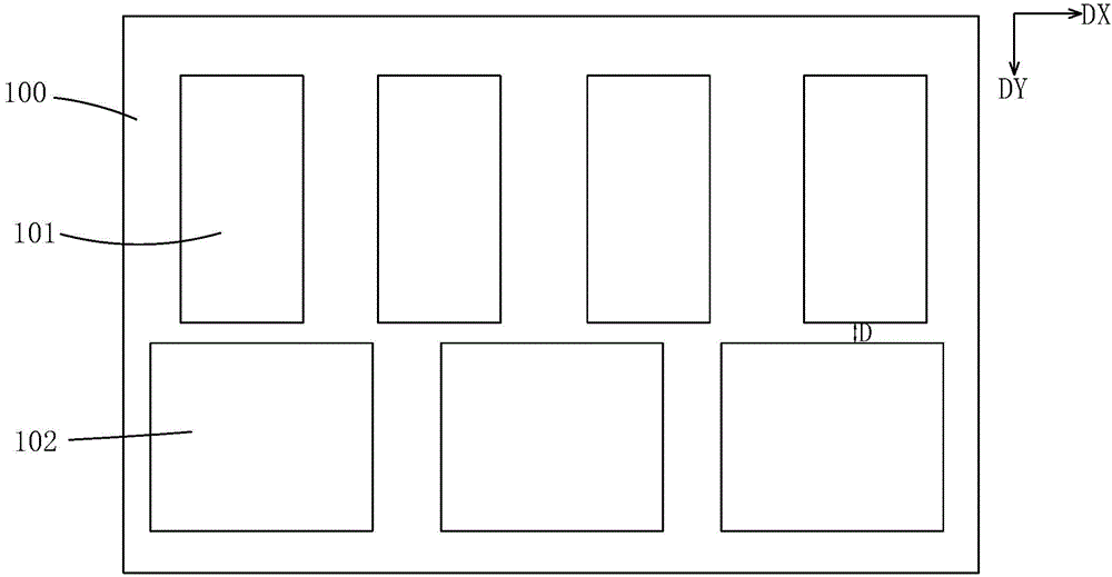
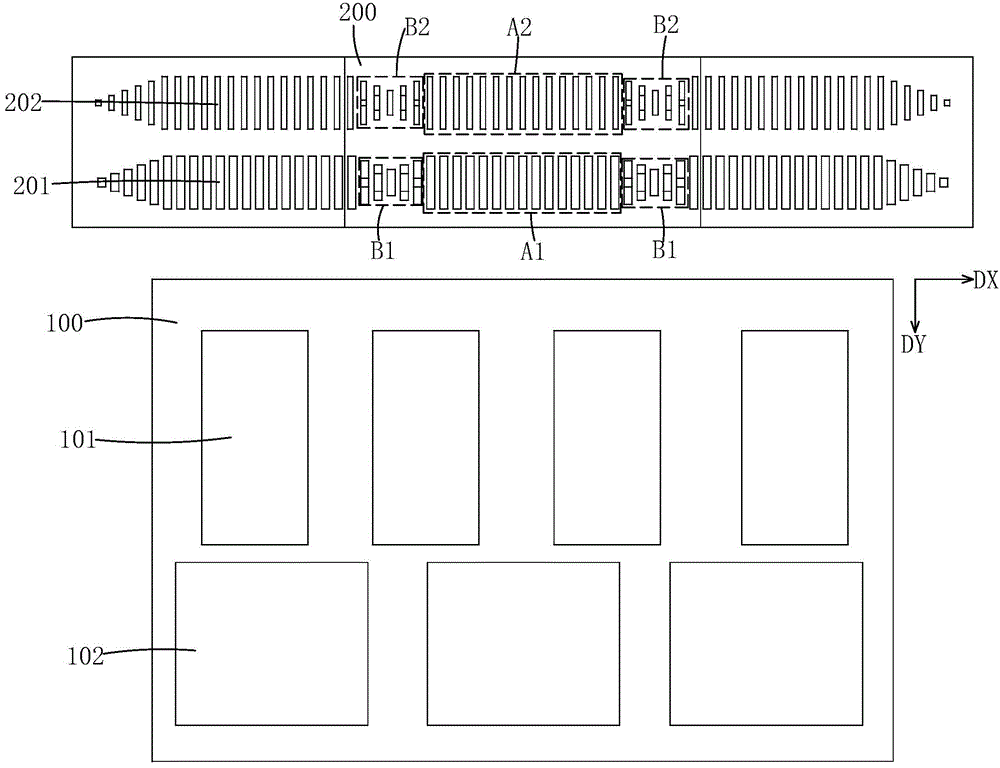
[0055] see Figure 8 , the present invention firstly provides a photomask for optical alignment, including a photomask body 2, a plurality of light-transmitting patterns arranged on the photomask body 2, and the plurality of light-transmitting patterns are arranged along the first direction DY one by one line arrangement.

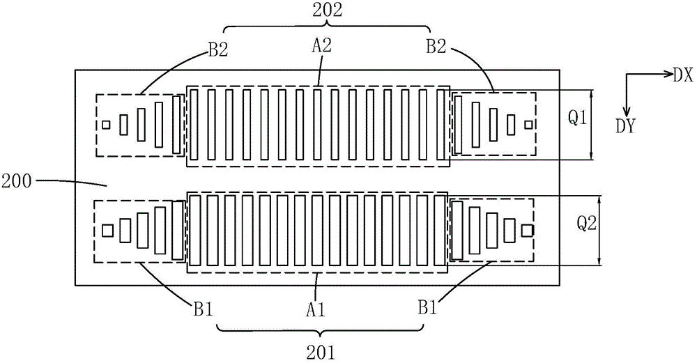
[0056] The plurality of light-transmitting patterns are arranged along a second direction DX perpendicular to the first direction DY, and each light-transmitting pattern includes a non-overlapping area that does not overlap with an adjacent photomask when in use, and is located at the non-overlapping area respectively. Overlapping regions that overlap adjacent reticles when used on the left and right sides of the region. ...


PUM


Abstract

The invention provides a photomask for photo alignment and a photo-alignment method. The photomask for photo alignment comprises a photomask body (2) and a plurality of light-transmitting patterns arranged on the photomask body (2), wherein the plurality of light-transmitting patterns are arrayed along the first direction (DY) line by line and are arranged along the second direction (DX) perpendicular to the first direction (DY); each light-transmitting pattern comprises a non-overlapping domain and overlapping domains, and the non-overlapping domain is not overlapped with adjacent photomasks during use; the overlapping domains are respectively positioned on the left side and the right side of the non-overlapping domain and are overlapped with the adjacent photomasks during use; the first direction (DY) is the translation forward direction of the photomask when the phototmask is used for exposure and alignment; one ends, towards the first direction (DY), of the light-transmitting patterns positioned in the overlapping domains are aligned to one ends, towards the first direction (DY), of the light-transmitting patterns positioned in the non-overlapping domain, so that the alignment effect can be improved, and the mura problem due to the fact that the unexposed domains or insufficiently-exposed domains exist when MMG products are aligned is avoided.

Description

technical field [0001] The invention relates to the manufacturing field of liquid crystal displays, in particular to a photomask for photo-alignment and a photo-alignment method. Background technique [0002] Liquid Crystal Display (LCD) has many advantages such as thin body, power saving, and no radiation, and has been widely used, such as LCD TV, mobile phone, personal digital assistant, digital camera, computer screen or notebook computer screen, etc. . [0003] Most of the existing liquid crystal displays are backlight liquid crystal displays, which include a housing, a liquid crystal panel disposed in the housing, and a backlight module disposed in the housing. Generally, a liquid crystal panel is composed of a color filter substrate (Color Filter, CF), a thin film transistor array substrate (Thin Film Transistor Array Substrate, TFT Array Substrate), and a liquid crystal layer (Liquid Crystal Layer) filled between the two substrates. , its working principle is to con...

Claims


Application Information

Patent Timeline
IPC IPC(8): G03F1/54G03F7/20G02F1/1337
CPCG02F1/133788G03F1/54
Inventor 韩丙
Owner TCL CHINA STAR OPTOELECTRONICS TECH CO LTD
Why Eureka
Try Eureka