A long button reset circuit of a device microprocessor and its composite function method

A microprocessor and reset circuit technology, which is applied in the reset circuit field, can solve problems such as large working current and complex circuit, and achieve the effects of increased reliability, high integration and beautiful equipment

Active Publication Date: 2018-01-16
CONTEC MEDICAL SYST
View PDF7 Cites 0 Cited by
  • Summary
  • Abstract
  • Description
  • Claims
  • Application Information

AI Technical Summary

Problems solved by technology

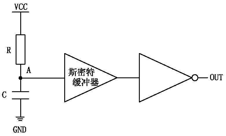
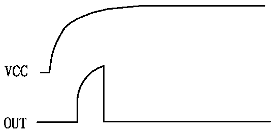
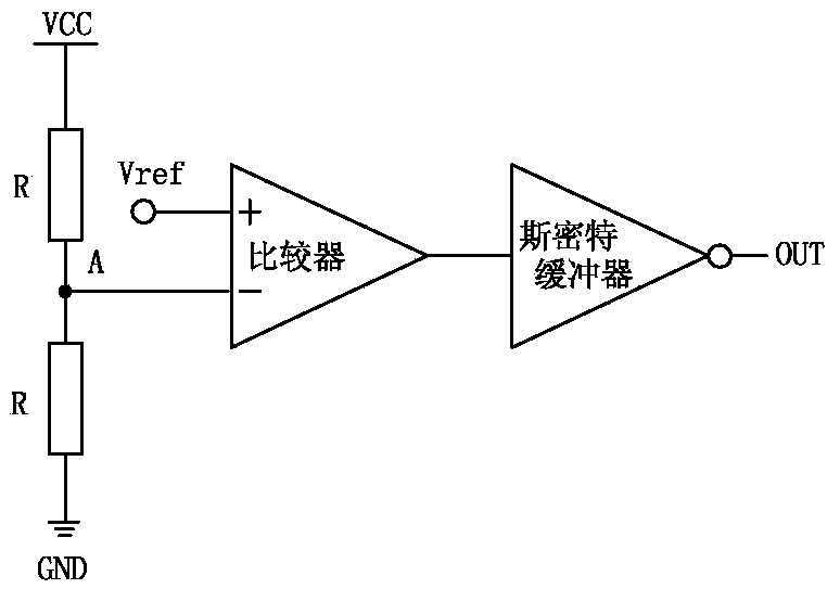
like Figure 4 As shown, the BOR circuit can detect the power supply voltage very well, but the circuit is more complicated, such as Vref needs to be stable, a reference voltage circuit is required, the comparator needs the power supply to provide current, and the operating current is large, etc., from reducing cost and power consumption Considering other aspects, it is not a good solution. After the circuit starts to work normally, if it needs to be reset and restarted again, if the above-mentioned traditional circuit is used, it is not a good choice due to its defects.

Method used


Image

  • A long button reset circuit of a device microprocessor and its composite function method
  • A long button reset circuit of a device microprocessor and its composite function method
  • A long button reset circuit of a device microprocessor and its composite function method

Examples


Embodiment 1

[0031] A long-press reset circuit of a microprocessor for equipment is aimed at the long-press reset circuit for a microprocessor of a handheld medical device, such as a hand-held electrocardiogram detector. Figure 5 As shown, the long key reset circuit includes a conventional reset circuit 2 of the device microprocessor circuit 1, and the microprocessor circuit 1 includes a power key (PWR KEY) 101 pin and a reset pin (RST) 102, the The conventional reset circuit is connected to the reset pin (RST). The conventional reset circuit can be a commonly used reset chip 809, or a resistance-capacitance circuit, or a combination of the two. The conventional reset circuit is After the external power supply is unstable or power-off, it is lower than the reset trigger threshold of the reset chip, and the reset chip outputs a reset signal to trigger the reset of the microprocessor. The power key (PWR KEY) pin of the microprocessor is connected to the positive pole Vbat (3.3V) of the powe...

Embodiment 2

[0037] This embodiment is a method for compounding functions of a microprocessor based on the reset circuit described in Embodiment 1, the circuit of which is as follows Figure 5 As shown, the content described in Embodiment 1 is also the content of this embodiment, which is the function method of pressing the switch until it is lifted after the microprocessor circuit is powered on, and the process is:

[0038] When the button is pressed for less than 30ms, it is judged as a wrong operation and the button does not work;

[0039] When the pressing time of the key is between 30ms and 1s, the system judges that it is a function key operation, and the display will display the function selection key for selection;

[0040] When the pressing time of the key is between 1s and 22s, the system determines that the application program is started and closed, and the display shows the application program start key and close key for selection;

[0041] When the button is pressed for more ...


PUM


Abstract

The invention discloses a long button reset circuit of a microprocessor for equipment and its compound function method. A charging and discharging circuit is added between the power key pin and the reset pin of the microprocessor, and the charging time is much longer than the discharging time. Features, through the judgment of the microprocessor, the multiple function multiplexing of the long button reset button is realized, which overcomes the problem that the traditional reset circuit set separately is prone to misoperation, and the reduced single reset button not only makes the device beautiful, but also facilitates the waterproofing of the device deal with. The present invention introduces the charging and discharging circuit into the solution, increases the reliability of reset, and avoids the influence of misoperation on the system. The present invention introduces the inverter chip into the scheme, which not only has high integration, but also adds the reminder function of loudspeaker and indicator light.

Description

technical field [0001] The present invention relates to the field of electronic circuits, in particular to a reset circuit of a device microprocessor and a compound function method thereof. It is a reset circuit that realizes a device with a built-in battery and no manual reset button, and solves the problem that current electronic devices encounter strong interference or When the system fails, it cannot actively resume normal operation. Background technique [0002] For integrated circuits such as ASIC and MCU, especially for digital integrated circuits, reset is one of the most important functions. Reset can initialize the circuit, so that the circuit can execute in the order of the designer's thought. If the reset circuit is not well designed, it may cause the circuit to enter an unknown state when the power is turned on or the power fluctuates, and the work will be chaotic. Although other measures can be taken in the circuit to remedy this erroneous state, such as soft...

Claims


Application Information

Patent Timeline
Patent Type & Authority Patents(China)
IPC IPC(8): G06F1/24
Inventor 胡坤许云龙刘晨亮黄杰邵建龙沈俊卿
Owner CONTEC MEDICAL SYST
Why Eureka
Try Eureka