Charging circuit used for mobile power supply and mobile power supply

A charging circuit and mobile power technology, applied in the direction of battery circuit devices, circuit devices, collectors, etc., can solve problems that affect the performance and reliability of mobile power sources, large power dissipation of mobile power sources, and the impact of electronic device performance, etc., to achieve improved charging Efficiency, Faster Charging, Ease of Implementation

Active Publication Date: 2015-10-07
QINGDAO GOERTEK
View PDF4 Cites 10 Cited by
  • Summary
  • Abstract
  • Description
  • Claims
  • Application Information

AI Technical Summary

Problems solved by technology

This "charging while discharging" design method will not only lead to a reduction in charging efficiency, but also generate a large power dissipation on the mobile power supply, resulting in serious heating of the mobile power supply.
When the operating temperature of the mobile power supply rises, it will affect the performance of the electronic devices inside the mobile power supply, and the higher the operating temperature, the lower the performance of the electronic devices, which seriously affects the performance and reliability of the mobile power supply.

Method used


Image

  • Charging circuit used for mobile power supply and mobile power supply
  • Charging circuit used for mobile power supply and mobile power supply
  • Charging circuit used for mobile power supply and mobile power supply

Examples


Embodiment 1

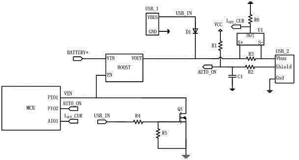
[0029] Embodiment one, see figure 1 As shown, in this embodiment, a charging interface USB_1 for external input power supply and a discharge interface USB_2 for external load are designed on the mobile power supply. The discharge interface USB_2 can be provided with one channel or multiple channels. In order to enable the input power supply USB_IN connected through the charging interface USB_1 to directly charge the external load, this embodiment connects the power supply pin VBUS of the charging interface USB_1 with the power supply pin Vbus of the discharge interface USB_2, so that the input power supply VBUS_IN can be connected to After being connected to the mobile power supply, it is directly transmitted to the external load through the power pin Vbus of the discharge interface USB_2 to charge it. In order to prevent the internal current of the mobile power supply from being fed back to the input power supply VBUS_IN, this embodiment connects an anti-reverse bias diode D...

Embodiment 2

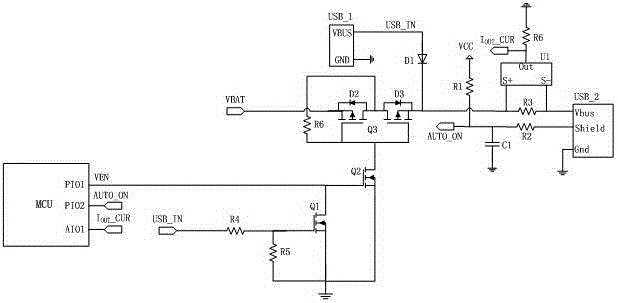
[0040] Embodiment two, see figure 2 As shown, in this embodiment, the charging interface USB_1 for external input power and the discharge interface USB_2 for external load are also designed on the mobile power supply. After the power supply pin VBUS of the charging interface USB_2 is connected in series with the anti-reverse bias diode D1, the power supply pin Vbus of the discharge interface USB_2 is connected. When the input power supply USB_IN is connected to the charging interface USB_1, the load inserted into the discharge interface USB_2 is directly Charge.

[0041] In order to control the built-in battery of the mobile power supply to stop charging the external load when the input power supply USB_IN is connected to the charging interface USB_1, this embodiment first designs a switch in the path where the battery is connected to the power pin Vbus of the discharge interface USB_2 circuit, the switch circuit can be formed by connecting two PMOS transistors, or directly ...

Embodiment 3

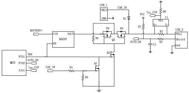
[0049] Embodiment three, see image 3 As shown, in this embodiment, the charging interface USB_1 for external input power and the discharge interface USB_2 for external load are also designed on the mobile power supply. After the power supply pin VBUS of the charging interface USB_2 is connected in series with the anti-reverse bias diode D1, the power supply pin Vbus of the discharge interface USB_2 is connected. When the input power supply USB_IN is connected to the charging interface USB_1, the load inserted into the discharge interface USB_2 is directly Charge.

[0050] In order to control the built-in battery of the mobile power supply to stop charging the external load when the input power supply USB_IN is connected to the charging interface USB_1, this embodiment designs a boost in the path where the battery is connected to the power pin Vbus of the discharge interface USB_2 The circuit BOOST and a switch circuit, the boost circuit BOOST can be formed by discrete compon...


PUM


Abstract

The invention discloses a charging circuit used for a mobile power supply and a mobile power supply. The charging circuit comprises a charging interface used for receiving an external input power supply, a discharging interface used for external connection with a load, a built-in cell used for storing electric energy, and a detection circuit used for detecting plugging states of the charging interface and the discharging interface. When the detection circuit detects that an input power supply accesses the charging interface, the input power supply is utilized to charge a load connected onto the discharging interface directly, the cell is controlled to stop charging the load. The mobile power supply utilizes an external input power supply to charge a load inserted into the mobile power supply directly when an input power supply is connected, thus the dissipation power of the mobile power supply can be lowered greatly, the heating value of the mobile power supply is lowered, that performances of an electronic device inside the mobile power supply cannot be lowered caused by too high working temperature is ensured, and the working reliability of the mobile power supply is raised.

Description

technical field [0001] The invention belongs to the technical field of charging and discharging circuits, and in particular relates to a circuit design suitable for a charging circuit of a mobile power supply. Background technique [0002] With the increasing popularity of wearable electronic products, their types are becoming more and more diverse, and their functions are becoming more and more diversified, and people use the wearable electronic products more and more frequently. Since wearable electronic products are generally small in size, the space reserved for batteries inside is very limited, and it is impossible to use larger batteries to power such electronic products. Limited by the volume of the battery, the capacity of the battery will not be too large, which will greatly limit the battery life of wearable electronic products and require frequent charging. [0003] In order to facilitate consumers to charge wearable electronic products or other portable digital...

Claims


Application Information

Patent Timeline
Patent Type & Authority Applications(China)
IPC IPC(8): H02J7/00
Inventor 王峰
Owner QINGDAO GOERTEK
Why Eureka
Try Eureka