
Disc type magnetism increasing DC generator

A technology of DC generators and generators, applied in the direction of generators/motors, AC/DC converters, synchronous motors with stationary armatures and rotating magnets, etc., which can solve the problems of inconvenient use, environmental pollution, and lack of pure magnetic energy DC generator and other problems, to achieve the effect of easy maintenance and easy use

Inactive Publication Date: 2015-10-07
徐占魁
View PDF0 Cites 2 Cited by
  • Summary
  • Abstract
  • Description
  • Claims
  • Application Information

AI Technical Summary

Problems solved by technology

Burning energy, polluting the environment, inconvenient to use
No pure magnetic energy DC generator

Method used


Image

  • Disc type magnetism increasing DC generator
  • Disc type magnetism increasing DC generator
  • Disc type magnetism increasing DC generator

Examples


Embodiment 1

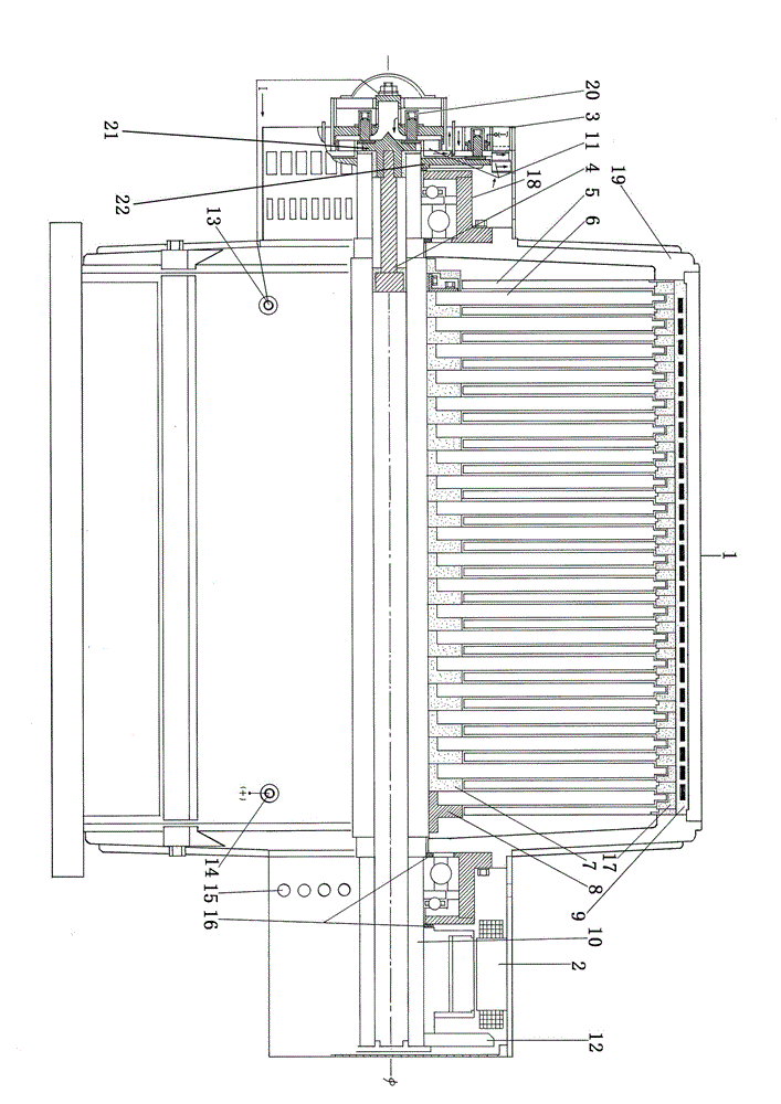
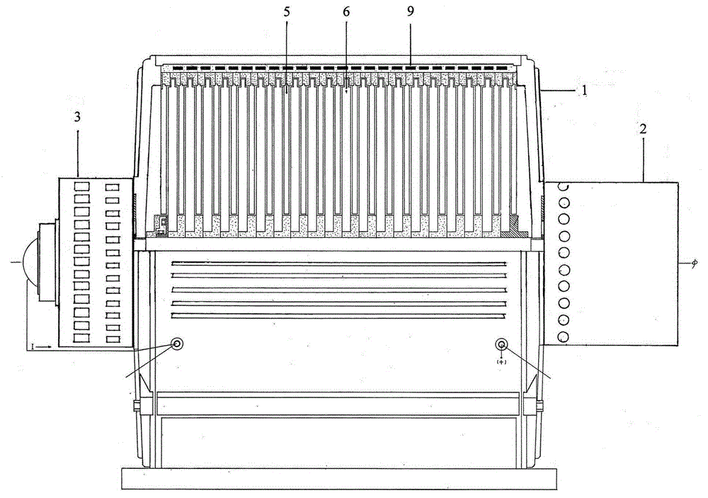
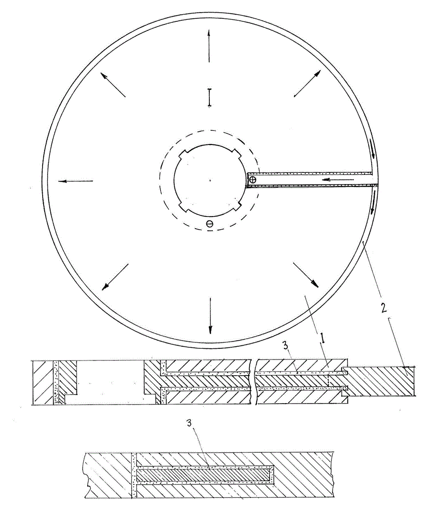
[0025] Such as figure 1 Shown, (horizontal) disk magnetized DC generator. It consists of three parts, 1 1. DC generator; Stator; By permanent magnetic disc 5 and structural ceramic insulating washer 17, spaced layer by layer with generator disc 6, constituting fixed permanent magnet magnetic source in casing coil 9. [ Case Coil ( Magnetic coil ) , made of aluminum strip or copper strip ( Wire ) It is wound into a coil matching the casing, and cast into the casing with insulating structural ceramics ] . rotor ; by the generator plate, ( Generating plate: It is composed of aluminum alloy generating plate, connected with copper alloy conductive ring, conductive ring connected with structural ceramic insulated bus bar, insulated bus bar is provided with positive connecting terminal, aluminum alloy generating plate is provided with negative connecting terminal ) And structural ceramics insulating electric disk seat 7, with permanent magnetic disk layer by layer interval, ...

Embodiment 2

[0031] Such as Figure 5 shown ,( Vertical and horizontal dual-purpose) disc-type magnetized DC generator, which is shown in the figure 1 On the basis of the horizontal disc magnetized DC generator, it is changed to form ( Vertical and horizontal) disc-type magnetized DC generator. with diagram 1 There are different places for horizontal DC generators, DC generators 7 Install the vertical frame on the negative side 10 . drag motor 4 Installed on the positive side of the DC generator. (The drive motor is a split structure) The rotor is installed on the shaft of the DC generator, and the stator is fixed on the end cover of the generator. Disc Brush Conductive Output Device 1 Installed on the extended part of the drag motor casing. ( DC generator shaft lengthened accordingly ), The positive conductive plate is connected to the conductive terminal in the shaft , The negative conductive disc is connected to the shaft 。 The bottom end cover is thickened so that the load...

Embodiment 3

[0033] Such as Figure 6 shown ,( vertical) disc magnetized DC generator, is in Fig. 5 (stand Horizontal and dual-purpose) based on the disc-type magnetized DC generator, after removing the horizontal frame. Constitute a (vertical) disk-type magnetized DC generator.


PUM


Abstract

A disc type magnetism increasing DC generator is a pure magnetic energy DC generator consisting of a drive motor, a DC generator, and a disc brush conductive output apparatus. The DC generator mainly consists of a permanent magnet magnetic source, a power generation disc rotor and a magnetism increasing coil. The power generation disc rotor cuts magnetic lines to generate a current, the current flows through the magnetism increasing coil to generate magnetoelectric potential, thereby enhancing magnetic energy of the DC generator, and raising output power of the DC generator. The DC generator and the drive motor operate coaxially, magnetic energy and power generation energy of the DC generator are much greater than magnetic energy and power consumption energy of the drive motor. Electric power outputted by the DC generator is much greater than electric power consumed by the drive motor. The disc type magnetism increasing DC generator can operate by using an own power generation power supply without any fuel and other power source after being started by a controller.

Description

technical field [0001] Pure magnetic energy DC generator. It can meet the electricity needs of industry, agriculture, civil and transportation. Background technique [0002] Now it is mainly nuclear power generation, hydropower generation, thermal power generation, and power generation based on energy sources. It burns energy, pollutes the environment, and is inconvenient to use. There is no pure magnetic energy DC generator. Contents of the invention [0003] 1. The disk-type magnetized DC generator is a pure magnetic energy DC generator composed of a drive motor, a DC generator, and a disk brush conductive output device. It is a high-energy and high-quality DC generator. Because the magnetic energy and power generation energy of the DC generator are much greater than the magnetic energy and power consumption energy of the drag motor, the electric power output by the DC motor is far greater than the electric power consumed by the drag motor. After the disk-type magnet...

Claims


Application Information

Patent Timeline
Patent Type & Authority Applications(China)
IPC IPC(8): H02K53/00H02N11/00
CPCH02K1/17H02K1/22H02K3/04H02K7/003H02K21/04H02K21/24H02K21/26H02K47/04H02K53/00
Inventor 徐占魁
Owner 徐占魁
Learn More