Current control power converter

A power converter and current control technology, which is applied in the direction of converting DC power input into DC power output, output power conversion device, and adjusting electric variables, etc., can solve the problem of increased switching loss, reduce switching loss, and increase switching frequency , Increase the effect of system loss

Inactive Publication Date: 2015-10-07
HARBIN INST OF TECH
View PDF4 Cites 3 Cited by
  • Summary
  • Abstract
  • Description
  • Claims
  • Application Information

AI Technical Summary

Problems solved by technology

[0003] The purpose of the present invention is to solve the problem of increasing the switching loss of the existing power converter while increasing the switching frequency. The present invention provides a current control type power converter

Method used


Image

  • Current control power converter
  • Current control power converter
  • Current control power converter

Examples


specific Embodiment approach 1

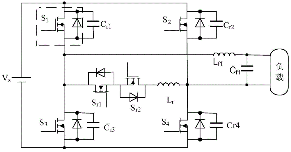
[0044] Specific implementation mode one: see figure 1 Describe this embodiment, the current control type power converter described in this embodiment, it includes power source V s , main circuit, auxiliary switch circuit and filter circuit;

[0045] The main circuit includes a power switch S 1 , power switch S 2 , power switch S 3 , power switch S 4 , capacitance C r1 , capacitance C r2 , capacitance C r3 and capacitance C r4 ,

[0046] power switch S 1 The current input terminal is connected to the power supply V s positive pole of the power switch S 3 The current output terminal is connected to the power supply V s The negative pole of the power switch S 1 The current output terminal is connected to the power switch S 3 The current input terminal of the power switch S 1 and power switch S 3 form a bridge arm,

[0047] power switch S 2 The current input terminal is connected to the power supply V s positive pole of the power switch S 4 The current output ...

specific Embodiment approach 2

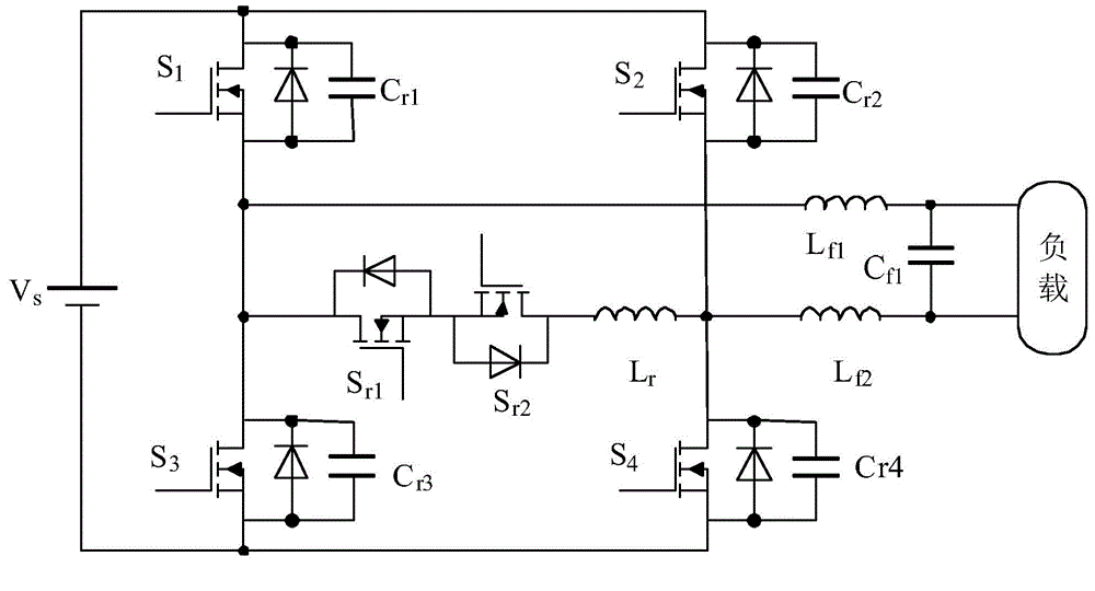
[0058] Specific implementation mode two: see figure 2 Describe this embodiment. The difference between this embodiment and the current-controlled power converter described in Embodiment 1 is that the filter circuit further includes an inductor L f2 ,

[0059] The inductance L f2 connected to the power switch S 4 of the current input terminal with a capacitor C f1 between the other end.

[0060] In this embodiment, the filter circuit is composed of two filter inductors and a filter capacitor, the two filter inductors are connected in series with the load, the load is located between the two filter inductors, and the series circuit formed by the two filter inductors and the load is connected in parallel to the main circuit At the connection point of the two semiconductor switching devices connected in series on the two bridge arms, the filter capacitor is connected in parallel with the load.

specific Embodiment approach 3

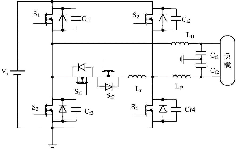
[0061] Specific implementation mode three: see image 3 Describe this embodiment. The difference between this embodiment and the current-controlled power converter described in Embodiment 2 is that the filter circuit further includes a capacitor C f2 ,

[0062] The capacitance C f2 connected in series with the inductor L f2 and capacitance C f1 between, and the capacitance C f2 and capacitance C f1 The connection point is connected to the power ground; the capacitor C f1 and capacitance C f2 Connect in parallel with the load after series connection.

[0063] In this embodiment, the filter circuit is composed of two filter inductors and two filter capacitors, the two filter inductors are connected in series with the load, the load is located between the two filter inductors, and the series circuit composed of the two filter inductors and the load is connected in parallel to the main circuit At the connection point of the two semiconductor switching devices connected in ...


PUM


Abstract

The invention relates to a current control power converter, and belongs to the motor control field. The problem is solved that in a present power converter, a switching frequency is raised while switching loss is increased. The power converter is mainly composed of a power supply, a main circuit, an auxiliary switching circuit and a filtering circuit. The main circuit is an H-bridge-shaped main circuit composed of two bridge arms. Each bridge arm is composed of two semiconductor switching elements in series connection. Each semiconductor switching element is in parallel connection with a capacitor. The two bridge arms of the main circuit are in parallel connection between the positive busbar and the negative busbar of the power supply. An auxiliary switch and an auxiliary inductor are in series connection to form an auxiliary switch circuit. Each of the two ends of the auxiliary switch circuit is connected with the connection point of two semiconductor switching elements in series connection of each bridge arm of the main circuit respectively. The current control power converter is mainly used for control of the motor.

Description

technical field [0001] The invention relates to a current control type power converter, which belongs to the field of motor control. Background technique [0002] In the high-precision servo drive system, in order to improve the response characteristics and efficiency of the system, usually adopt Figure 7 The PWM power conversion circuit shown has the advantages of low cost, high efficiency, and simple control. However, since the power device works in the switching state, its output current waveform has a large pulsating component, so it is difficult to achieve high-precision control. will cause instability. In the occasions that require extremely high positioning accuracy and smooth operation, it is usually necessary to increase the switching frequency, but this will increase the switching loss, which not only reduces the system efficiency and reliability, but also increases the system volume and weight. Contents of the invention [0003] The purpose of the present inv...

Claims


Application Information

Patent Timeline
Patent Type & Authority Applications(China)
IPC IPC(8): H02M3/155H02M1/14
Inventor 寇宝泉张海林贺铁锐牛旭
Owner HARBIN INST OF TECH
Why Eureka
Try Eureka