
Inverter power source device

A technology of inverter power supply and high-frequency inverter circuit, which is applied to output power conversion devices, photovoltaic power generation, electrical components, etc. The effect of capacity expansion, simple control and overall efficiency improvement

Inactive Publication Date: 2013-08-21
SUNGROW POWER SUPPLY CO LTD
View PDF4 Cites 2 Cited by
  • Summary
  • Abstract
  • Description
  • Claims
  • Application Information

AI Technical Summary

Problems solved by technology

[0005] Depend on figure 2 It can be seen that the output of the flyback circuit in the front stage of the traditional micro-inverter is not a constant DC, and reactive power regulation cannot be realized.
In addition, in the micro-inverter with this structure, the transformer T is not only used for energy storage, but also for energy transmission, so an air gap needs to be opened, so the front-stage flyback circuit cannot increase the power, even if Great power, low efficiency
Moreover, in order to achieve soft switching, it is not only necessary to select a higher-performance controller, but also to design more complex, sometimes it is necessary to add some auxiliary circuits

Method used


Image

  • Inverter power source device
  • Inverter power source device
  • Inverter power source device

Examples


Embodiment Construction

[0043] In order to enable those skilled in the art to better understand the solutions of the embodiments of the present invention, the embodiments of the present invention will be further described in detail below with reference to the accompanying drawings and implementation manners.

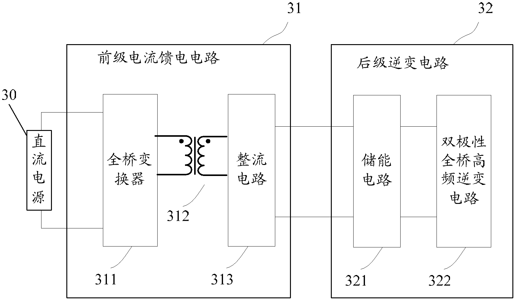
[0044] Such as image 3 What is shown is a schematic diagram of the principle of an inverter power supply device according to an embodiment of the present invention.

[0045] The inverter power supply device is used to convert the DC power output by the DC power supply 30 into AC power, and includes a front-stage current feeder circuit 31 and a rear-stage inverter circuit 32. Wherein, the current feeding circuit 31 includes: a full-bridge converter 311, an isolation transformer 312, and a rectifier circuit 313 connected in series in sequence; the rear-stage inverter circuit 32 includes: a storage circuit 321 and a bipolar full-bridge high Frequency inverter circuit 322. Wherein, the energy storage ...


PUM


Abstract

The invention discloses an inverter power source device used for converting a direct current output by a direct-current power source into an alternating current. The inverter power source device comprises a preceding-stage current feed circuit and a posterior-stage inverter circuit. The current feed circuit comprises a full-bridge converter, an isolation transformer and a rectifying circuit, wherein the full-bridge converter, the isolation transformer and the rectifying circuit are connected in series in sequence. The posterior-stage inverter circuit comprises a tank circuit and a bipolar full-bridge high-frequency inverter circuit, wherein the tank circuit is connected between two output ends of the current feed circuit, and the bipolar full-bridge high-frequency inverter circuit is used for converting direct voltage output by the current feed circuit into alternating voltage. Due to the inverter power source device, under the condition that energy conversion efficiency is ensured, complexity of control can be reduced, and reactive power adjusting and power expansion are convenient.

Description

Technical field [0001] The invention relates to the technical field of voltage conversion, in particular to an inverter power supply device. Background technique [0002] At present, in the field of photovoltaic power generation, integrated grid-connected power generation is still the mainstay. The grid-connected photovoltaic power generation system converts the DC power of the solar panels into alternating current with the same frequency and phase as the grid voltage through the grid-connected inverter and transmits it to the grid. Therefore, the grid-connected inverter is the core equipment of the photovoltaic grid-connected power generation system. Its reliability, efficiency and safety will affect the entire power generation system and directly affect the power generation capacity and stable operation of the power station. [0003] Photovoltaic grid-connected micro-inverters (micro-inverters for short) are connected to a single photovoltaic module, which can directly convert t...

Claims


Application Information

Patent Timeline
Patent Type & Authority Applications(China)
IPC IPC(8): H02M7/537H02M3/335
CPCY02E10/56
Inventor 赵为史晓峰胡兵
Owner SUNGROW POWER SUPPLY CO LTD
Learn More