Grid driving system used for LED lamp protection system based on boost voltage stabilizing circuit

A voltage stabilizing circuit and protection system technology, applied in the direction of electric lamp circuit layout, electric light source, lighting device, etc., can solve the problems of voltage fluctuation and other problems, achieve the effect of stable working voltage, avoid external electromagnetic interference, and reduce current noise

Inactive Publication Date: 2015-10-07
成都威邦科技有限公司
View PDF3 Cites 1 Cited by
  • Summary
  • Abstract
  • Description
  • Claims
  • Application Information

AI Technical Summary

Problems solved by technology

[0004] The purpose of the present invention is to overcome the defect that the current gate drive circuit is easily affected by voltage fluctuations during operation, and to provide a gate drive system for LED lamp protection systems based on a boost voltage regulator circuit

Method used


Image

  • Grid driving system used for LED lamp protection system based on boost voltage stabilizing circuit

Examples


Embodiment

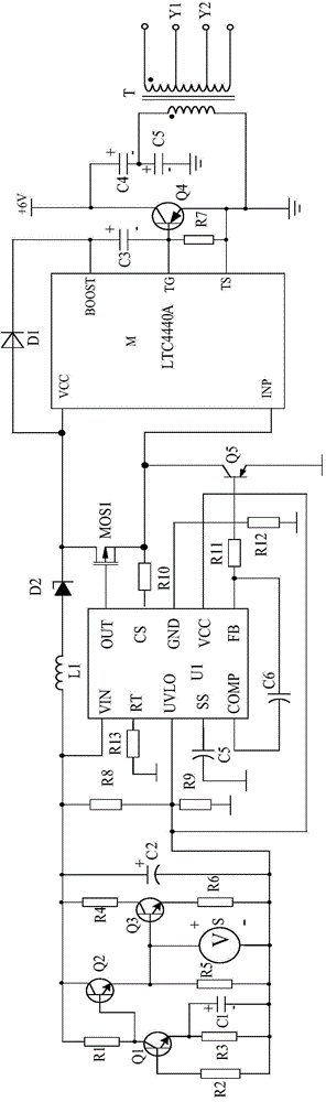
[0016] like figure 1 As shown, the present invention is composed of transistor Q4, transformer T, driver chip M, switching current source, diode D1, capacitor C3, resistor R7, capacitor C4, capacitor C5 and boost voltage regulator circuit. When connecting, the boost voltage regulator circuit needs to be connected in series between the VCC pin and the INP pin of the driver chip M, and the switching current source needs to be connected to the input terminal of the boost voltage regulator circuit. The diode D1 is connected in series between the VCC pin and the BOOST pin of the driver chip M, the capacitor C3 is connected in series between the BOOST pin and the TG pin of the driver chip M, and the resistor R7 is connected in series with the driver chip M. Between TG pin and TS pin.

[0017] The base of the transistor Q4 is connected to the TG pin of the driving chip M, its collector is grounded after passing through the capacitor C4 and capacitor C5 in sequence, and its emitter i...


PUM


Abstract

The invention discloses a grid drive system for an LED lamp protection system. The grid drive system is characterized by mainly comprising a transformer T, a drive chip M, a switchable current source connected between a VCC pin and an INP pin of the drive chip M in series, a diode D1 connected between the VCC pin and a BOOST pin of the drive chip M in series, a capacitor C3 connected between the BOOST pin and a TG pin of the drive chip M in series, a resistor R7 connected between the TG pin and a TS pin of the drive chip M in series, and a transistor Q4, wherein the base of the transistor Q4 is connected with the TG pin of the drive chip M, the collector of the transistor Q4 is grounded after passing through a capacitor C4 and a capacitor C5, and the emitter of the transistor Q4 is grounded. The grid drive system for the LED lamp protection system not only has the short circuit protection, over-voltage protection and open circuit protection functions, but also is low in power consumption, and the starting time of the system is only one fourth that of a traditional grid drive circuit.

Description

technical field [0001] The invention relates to a driving system, in particular to a grid driving system for an LED lamp protection system based on a voltage boosting and stabilizing circuit. Background technique [0002] At present, due to the characteristics of low energy consumption, long service life, safety and environmental protection, LED lamps have become one of the mainstream products for people's living lighting. Since LED lamps are different from traditional incandescent lamps, they need to be driven by a dedicated drive circuit, so there are various protection systems on the market to prevent the drive system from being interfered by internal or external adverse factors. [0003] The grid drive circuit is an important part of the LED lamp protection system, and its operating speed and performance stability directly determine the range of use and performance of the LED lamp protection system. However, at present, these gate drive circuits are easily affected by v...

Claims


Application Information

Patent Timeline
Patent Type & Authority Applications(China)
IPC IPC(8): H05B37/02
Inventor 周小玲
Owner 成都威邦科技有限公司
Why Eureka
Try Eureka