
Intelligent burning-preventive electronic deinsectization lamp control circuit

A technology for controlling circuits and insect-killing lamps, which is applied to electrical components, equipment that produces electric shocks, etc., can solve problems such as long-term uninterrupted discharge, unstable circuit current and voltage, chip or circuit burnout, etc., and achieve good results. Intelligent anti-burning effect and fast adjustment ability effect

Inactive Publication Date: 2015-10-07
WEIFANG YOURONG IND
View PDF0 Cites 3 Cited by
  • Summary
  • Abstract
  • Description
  • Claims
  • Application Information

AI Technical Summary

Problems solved by technology

[0002] As we all know, many mosquitoes have phototaxis and odortaxis. Using electronic lamps to eliminate pests is a very well-known technology. There are also many electronic insect repellents on the market. Most of them use high-voltage electrodes. When mosquitoes and moths touch After reaching the high-voltage electrode, it was instantly electrocuted to death. However, the common problem of the electronic pest control lamp is that after a period of use, the internal circuit and electrical components are burned out. After analysis, it is found that the main reasons are as follows: When encountering Larger moths enter the high-voltage electrodes. Although the moths can be electrocuted instantly, the dead bodies of the moths are still adsorbed on the high-voltage electrodes, and the electronic pest control lamps still release high voltage. Uninterrupted discharge for a long time, so it is easy to burn the equipment, and cannot achieve the effect of killing insects. In addition, when a short circuit is caused by external factors, the existing insect killing lamp cannot analyze whether it is a short circuit or flying insects enter the high-voltage electrode, resulting in a circuit breaker. The medium current and voltage are unstable, and it is easy to burn the chip or circuit

Method used


Image

  • Intelligent burning-preventive electronic deinsectization lamp control circuit

Examples


Embodiment Construction

[0020] For ease of explanation, below in conjunction with accompanying drawing, the control circuit of the intelligent anti-burning electronic pest control lamp of the patent application is described in detail.

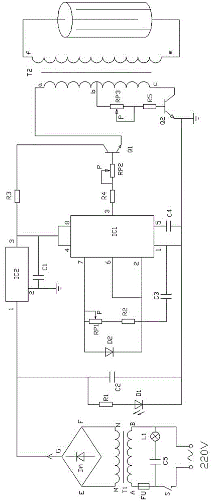
[0021] like figure 1 As shown in , an intelligent anti-burning electronic pest control circuit includes a rectification module, a boost module and a regulation control module. An adjustment control module is connected to the output terminal of the diode Dm, and the adjustment control module includes a three-terminal voltage stabilizing integrated chip IC2 and a time base integrated chip IC1.

[0022] The power supply is a 220V AC power supply, the live wire of the power supply is connected to one end of the switch S, the other end of the switch S is connected to one end of the capacitor C5, the other end of the capacitor C5 is connected to one end of the indicator light L1, and the other end of the indicator light L1 One end is connected to the neutral wire of the po...


PUM


Abstract

The invention provides an intelligent burning-preventive electronic deinsectization lamp control circuit which comprises a rectifier module, a booster module and an adjusting control module. The rectifier module comprises a rectifier diode Dm, an input end of the rectifier diode Dm is connected with a power source while an output end of the same is connected with the adjusting control module, and the adjusting control module comprises a three-end voltage-stabilizing integrated chip IC2 and a time-base integrated chip IC1. The circuit comprises the rectifier module, the booster module and the adjusting control module, the adjusting control module comprises the three-end voltage-stabilizing integrated chip IC2 and the time-base integrated chip IC1, stability of voltage in the circuit is realized by utilizing the three-end voltage-stabilizing integrated chip, and the voltage in the circuit is adjusted by utilizing the time-base integrated chip, so that the circuit has good intelligent burning-preventive effect. In addition, the circuit has high adjusting capability, and voltage fluctuation time duration with a positive-negative 5V deviation range does not exceed 0.3s.

Description

technical field [0001] The patent application of the present invention relates to the fields of bioengineering and electronic technology, in particular to an electronic pest control lamp, specifically to a control circuit of an intelligent anti-burning electronic pest control lamp. Background technique [0002] As we all know, many mosquitoes have phototaxis and odortaxis. Using electronic lamps to eliminate pests is a very well-known technology. There are also many electronic insect repellents on the market. Most of them use high-voltage electrodes. When mosquitoes and moths touch After reaching the high-voltage electrode, it was instantly electrocuted to death. However, the common problem of the electronic pest control lamp is that after a period of use, the internal circuit and electrical components are burned out. After analysis, it is found that the main reasons are as follows: When encountering Larger moths enter the high-voltage electrodes. Although the moths can be e...

Claims


Application Information

Patent Timeline
Patent Type & Authority Applications(China)
IPC IPC(8): H05C1/06
Inventor 王胜
Owner WEIFANG YOURONG IND
Learn More