Coil unit and device for the inductive transfer of electrical energy

A coil unit, a technology for transmitting electrical energy, applied in circuit devices, transportation and packaging, electrical components, etc., can solve problems such as non-compliance

Inactive Publication Date: 2015-10-07
CONDUCTIX WAMPFLER
View PDF13 Cites 22 Cited by
  • Summary
  • Abstract
  • Description
  • Claims
  • Application Information

AI Technical Summary

Problems solved by technology

However this requirement cannot be complied with by means of co

Method used


Image

  • Coil unit and device for the inductive transfer of electrical energy
  • Coil unit and device for the inductive transfer of electrical energy
  • Coil unit and device for the inductive transfer of electrical energy

Examples


Embodiment Construction

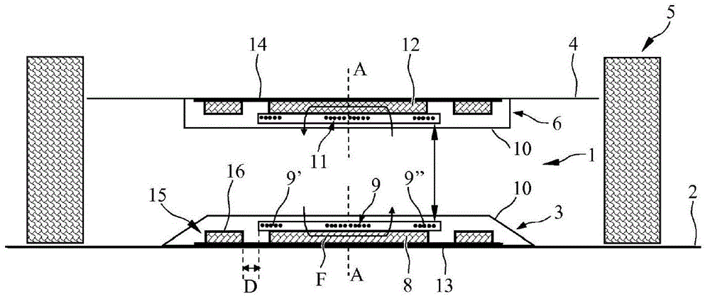
[0046] figure 1 Schematically shows a schematic sectional view of a device 1 according to the invention for connecting a primary coil unit 3 according to the invention arranged on a roadway 2 with a coil unit according to the invention arranged on the vehicle floor 4 of an electric vehicle 5 . Electric energy is inductively transmitted between the secondary coil units 6 .

[0047] as by figure 1 It is known that the primary coil unit 3 is arranged above the roadway 2 . However, primary coil unit 3 can also be sunk into or below roadway 2 . Furthermore, the secondary coil unit 6 can be integrated into the vehicle underbody 4 . As can be easily seen, the height spacing H between the primary coil unit 3 and the secondary coil unit 6 is relatively large and typically 10 to 20 cm.

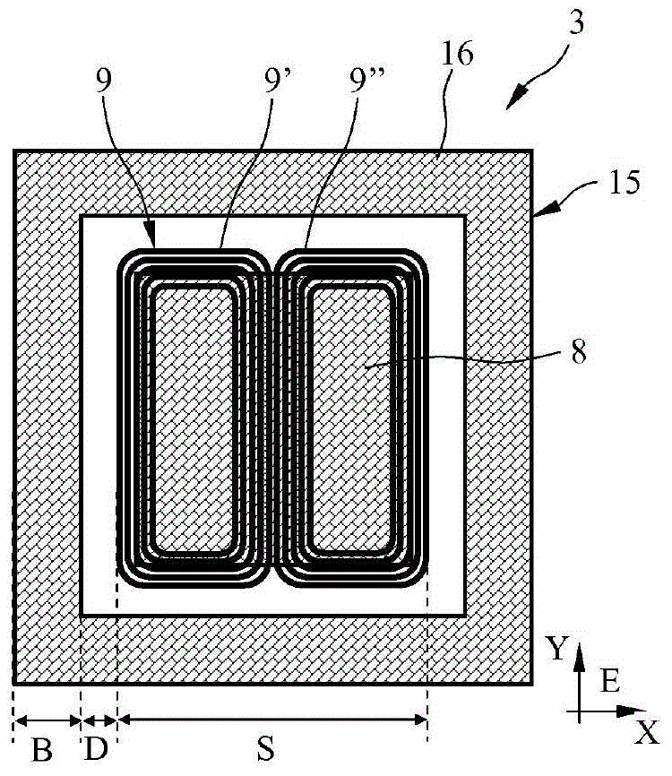
[0048] The primary coil unit 3 has a housing 7 with a magnetic flux conducting unit 8 and a primary coil 9 arranged thereon. Housing 7 is made of a magnetically permeable material, preferably pla...


PUM


Abstract

The invention relates to a coil unit (3; 6) for the inductive transfer of electrical energy, comprising a coil (9; 11; 31; 32; 33; 39) and a flux guide unit (8; 12; 34; 40) for guiding a magnetic flux generated during operation of the coil (9; 11; 31; 32; 33; 39), wherein the coil (9; 11; 31; 32; 33; 39) and/or the flux guide unit (8; 12; 34; 40) are surrounded by stray field screening (15; 16, 16'; 20; 23, 26; 26'; 27; 27'), and a device (1) for the inductive transfer of electrical energy between a fixed primary coil unit (3) and a secondary coil unit (6) mounted on a movable load. The invention solves the problem of providing a coil unit and a device for the inductive transfer of electrical energy that have a small and weak stray field, do not exceed the desired specifications for the maximum flux density outside the vehicle, and improve the efficiency of inductive energy transfer to the vehicle, comprising a coil unit in which the stray field screening (15; 16; 20; 23; 26, 27; 35; 36; 37, 38) is mounted at a lateral distance (D) from the flux guide unit (8; 12; 34; 40) and the coil (9; 11; 31; 32; 33; 39; 41).

Description

technical field [0001] The invention relates to a coil unit according to the preamble of claim 1 , a device for inductively transmitting electrical energy according to the preamble of claim 20 and the use of a coil unit according to the preamble of claim 22 . Background technique [0002] It is known in the field of inductive energy transmission to movable loads, in particular electric vehicles such as cars, buses or vans and trains, that batteries installed in electric vehicles pass through secondary coils arranged on the underbody of the vehicle Charged by a stationary primary coil. [0003] Document DE 693 13 151 T2 discloses such a battery charging system for charging electric vehicle batteries. There, however, the user must manually connect the primary coil arrangement with the secondary coil arrangement on the vehicle. This has the disadvantage that the user has to get out of the vehicle and connect the primary coil structure to the secondary coil structure in a comp...

Claims


Application Information

Patent Timeline
IPC IPC(8): H01F38/14H01F27/36
CPCH01F27/365B60L11/182B60L2200/18B60L2200/26B60L2200/36B60L2270/147H01F38/14Y02T10/7005Y02T90/122Y02T90/14Y02T10/7072H01F27/2871B60L53/12H01F27/36Y02T10/70H01F27/366H02J50/70H02J50/10Y02T90/12H01F27/24H01F27/2823
Inventor A·格林V·费伊梯西
Owner CONDUCTIX WAMPFLER
Why Eureka
Try Eureka