Optical flow control chip utilizing impinging stream and optical scattering force and application thereof for sorting micro-nano particles

An optofluidic and impinging flow technology, which is applied to laboratory containers, grading, and solid separation, can solve problems such as simple, non-invasive, high-speed, and high-efficiency sorting, and achieve simple, Improve the separation speed and efficiency, the effect of simple equipment

Active Publication Date: 2015-10-14
WUHAN UNIV
View PDF5 Cites 6 Cited by
  • Summary
  • Abstract
  • Description
  • Claims
  • Application Information

AI Technical Summary

Problems solved by technology

None of the above methods can meet the requirements of simple, harmless, high-speed and high-efficiency sorting

Method used


Image

  • Optical flow control chip utilizing impinging stream and optical scattering force and application thereof for sorting micro-nano particles
  • Optical flow control chip utilizing impinging stream and optical scattering force and application thereof for sorting micro-nano particles

Examples


Embodiment Construction

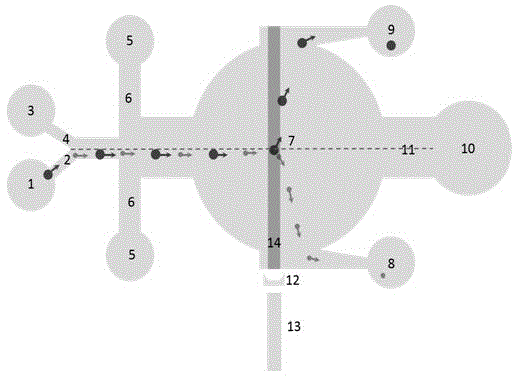
[0018] The optofluidic chip of the present invention is manufactured by standard photolithography method. First, use L-Edit to draw the template picture according to the previously designed chip structure. Then coat a layer of SU-8 photoresist on the silicon wafer to obtain a PDMS mold. After obtaining the PDMS layer and irreversibly binding it to the PDMS-attached glass slide with oxygen plasma, the optofluidic chip was baked at 75°C for 1 hour to enhance hydrophobicity and eliminate residual water.

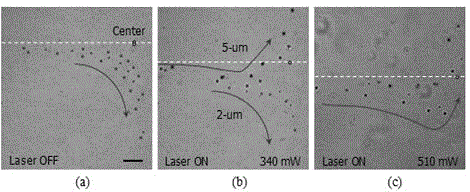
[0019] An application example of the optofluidic chip of the present invention, wherein the flow rate of the auxiliary inlet and the sample inlet is 0.06 μL / min, the flow rate of the sheath inlet is 0.96 μL / min, and the flow rate of the impingement inlet is 2.04 μL / min. The optimal separation power of the laser is 560 mW (considering about 40% dissipation, the actual power is about 340 mW).

[0020] The optofluidic chip of the present invention generally utilizes the combined ...


PUM


Abstract

The invention relates to an optical flow control chip utilizing impinging stream and optical scattering force and application thereof for sorting micro-nano particles, belonging to the field of optical flow control chips. The optical flow control chip comprises a cylindrical optical separation cavity, wherein one side of the optical separation cavity is connected with an impinging stream inlet through an impinging stream channel, the other side of the optical separation cavity is provided with an auxiliary flow inlet and a sample flow inlet, the center line of a channel formed by converging of an auxiliary flow channel and a sample flow channel and the center line of the impinging stream channel are positioned on the same straight line, and two sides of the channel formed by converging of the auxiliary flow channel and the sample flow channel are respectively connected with an inlet of sheath flow through a sheath flow channel, and then are connected with the optical separation cavity; an optical fiber groove with a collimating lens, as well as a large-particle outlet and a small-particle outlet, is further formed in the optical separation cavity. According to the invention, a point with the minimal speed value is formed at the center of an optical sorting cavity, so that an optical scattering force can be used for sorting particles at the point, the average speed of sorting operation by the optical force is greatly improved, and the sorting precision and efficiency are improved.

Description

technical field [0001] The invention relates to an optofluidic chip utilizing impact flow and optical scattering force and its application for sorting micro-nano particles, belonging to the field of optofluidic chips. Background technique [0002] Compared with other purely passive hydrodynamic separation methods, the optical separation method has extremely high advantages such as active electrophoresis and acoustophoresis methods. Passive methods are mainly based on hydraulic focusing methods but suffer from structural complexity. The electrophoresis method utilizes the principle that molecules (such as proteins, polypeptides, nucleic acids, etc.) have different charges and have different displacements under an external electric field. However, in order to achieve high-speed assays, electrophoresis is limited by the pH value and high voltage (such as 53 kV / cm) of the environment. These environmental parameters will destroy active biomacromolecules. Acoustophoresis is simi...

Claims


Application Information

Patent Timeline
Patent Type & Authority Applications(China)
IPC IPC(8): B01L3/00B07B13/00B07B13/16B07B13/18
Inventor 杨奕胡华天吴唯
Owner WUHAN UNIV
Why Eureka
Try Eureka