Trepanning machining mechanism

A technology of hole processing and fixed handle, which is applied in the field of hole processing mechanism, can solve the problems of complex structure of the hole punching device and poor hole punching effect, and achieve the effects of simple structure, guaranteed hole punching effect, and easy operation

Inactive Publication Date: 2015-10-14
CHENGDU LIXIN SCI & TECH
View PDF8 Cites 2 Cited by
  • Summary
  • Abstract
  • Description
  • Claims
  • Application Information

AI Technical Summary

Problems solved by technology

[0003] In order to solve the defects of the existing punching device such as complicated structure and poor punching effect, the present invention provides a punching mechanism

Method used


Image

  • Trepanning machining mechanism
  • Trepanning machining mechanism
  • Trepanning machining mechanism

Examples


Embodiment 1

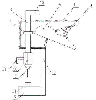
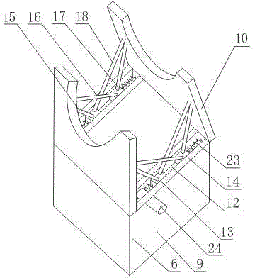
[0023] like figure 1 , figure 2 As shown, a hole processing mechanism includes a fixed handle 1 with a cavity structure, a sliding rod 2 that is slidably arranged in the fixed handle 1 through the upper and lower end faces of the fixed handle 1 , and a drill 3 that is arranged at the bottom of the sliding rod 2 , the movable handle 4 hinged on the fixed handle 1, the support rod 5 fixed on the lower end of the fixed handle 1 and the adjustment seat 6 connected with the support rod 5; one side of the fixed handle 1 is fully open, and also includes a On the chuck 7, one end of the movable handle 4 is connected to the chuck 7, and the other end runs through the opening on one side of the fixed handle 1 and is located outside the fixed handle 1; Spring 8; the adjusting seat 6 includes a base 9, a cover 10 hinged on both sides of the upper surface of the base 9 respectively, the side of the cover 10 has a semicircular groove, and the semicircular grooves on the sides of the two c...

Embodiment 2

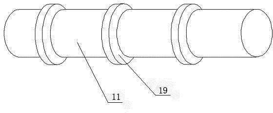
[0026] This embodiment is on the basis of embodiment 1, as image 3 As shown, retaining rings 19 are evenly distributed on the bottom rod 11 from bottom to top along the axis direction of the bottom rod 11 , and the diameter of the retaining rings 19 is larger than that of the bottom rod 11 .

[0027] When it is necessary to adjust the distance between the material to be punched and the drill pin 3, the cover 10 hinged on both sides of the upper surface of the base 9 is opened, and the bottom rod 11 is placed in the base 9. When the bottom rod 11 reaches the During proper position, cover 10 on both sides is covered, because back-up ring 19 diameters are greater than bottom rod 11 diameters, the position of bottom rod 11 will be fixed. The first pull rod A15 and the second pull rod A16 support one of the cover 10 when the cover 10 is opened, and the first pull rod B17 and second pull rod B18 support the other cover 10 . When the cover 10 on both sides needs to be closed, the s...

Embodiment 3

[0029] On the basis of Embodiment 1, this embodiment also includes a taper head 20 fixed at the lower end of the slide rod 2 through screw connection, and the drill needle 3 is fixed at the bottom of the taper head 20 . It also includes a handle 21 fixed on the side surface of the cone head 20 .

[0030] When the material to be punched is thick or the strength of the hand is difficult to complete the hole, while the above operation is performed, rotate the handle 21 with the other hand, and the drill needle 3 will move up and down and act on the material to be punched again, thereby assisting Finish punching.


PUM


Abstract

The invention discloses a trepanning machining mechanism. The trepanning machining mechanism comprises a fixed handle of a cavity structure, a sliding rod, a drill point arranged at the bottom of the sliding rod, a movable handle hinged to the fixed handle, a supporting rod fixed to the lower end of the fixed handle and an adjusting base connected with the supporting rod, wherein the sliding rod penetrates through openings in the upper end face and the lower end face of the fixed handle and is arranged in the fixed handle in a sliding mode. According to the trepanning machining mechanism, one end of the movable handle is connected with a clamping disc, the movable handle is hinged to the fixed handle, the movable handle is tightened inwards with force, and the drill point can downwards act on an object to be punched for punching the object. A punching device in the trepanning machining mechanism is simple in structure and easy to operate.

Description

technical field [0001] The invention relates to a punching mechanism, in particular to a hole processing mechanism. Background technique [0002] At present, punching is done by using punching pliers. The punching pliers are composed of a handle, a punching head, a pressing sheet, and a hole seat. The punching head is connected to one handle, the hole seat is connected to the other handle, and the handles on both sides Riveted together by rivets, the cross-sectional shape of the punching head is arbitrary, the pressing piece and the hole seat are provided with holes corresponding to the shape of the punching head, when the handle is held, the punching head can pass through the pressing piece and the hole seat , the punching action is completed by impacting the punching head on the pressing sheet and the hole seat. The structure of the traditional punching device is not only complicated, but also difficult to completely penetrate the plate when encountering a thicker plate. ...

Claims


Application Information

Patent Timeline
Patent Type & Authority Applications(China)
IPC IPC(8): B26F1/24B26F1/32
CPCB26F1/24B26F1/32
Inventor 赖金元
Owner CHENGDU LIXIN SCI & TECH
Why Eureka
Try Eureka