
Chassis structure of suspension frame electric vehicle

A technology for electric vehicles and frames, applied in suspension, elastic suspension, steering mechanism, etc., can solve the problems of limited driving capacity and bearing capacity, decreased stability, wear resistance, etc., to achieve large bearing capacity, driving Stability-enhancing effect

Inactive Publication Date: 2015-10-14
邹帆
View PDF8 Cites 4 Cited by
  • Summary
  • Abstract
  • Description
  • Claims
  • Application Information

AI Technical Summary

Problems solved by technology

[0002] The suspension method adopted by the existing automobile chassis cannot actively and quickly change the suspension height. When the inclination of the road surface changes, the inclination angle of the vehicle body will inevitably be changed, thereby reducing the stability or even overturning. And the front and rear wheel bases are reduced, which makes the vehicle easy to overturn in the horizontal and vertical directions; this feature limits the driving capacity and carrying capacity of the vehicle on complex terrain, making it only suitable for use on roads, and only for people to walk. There is currently no ideal maneuvering method for walking paths, field ridges and other terrains
[0003] Existing bionic walking robots use a very complex multi-degree-of-freedom hydraulic drive method. This bionic walking method is suitable for uneven ground but is not as good as wheeled vehicles on relatively flat roads. Its operating power efficiency is low and its speed is slow. Not resistant to wear

Method used


Image

  • Chassis structure of suspension frame electric vehicle
  • Chassis structure of suspension frame electric vehicle
  • Chassis structure of suspension frame electric vehicle

Examples


Embodiment Construction

[0020] The present invention will be described in further detail below in conjunction with the accompanying drawings.

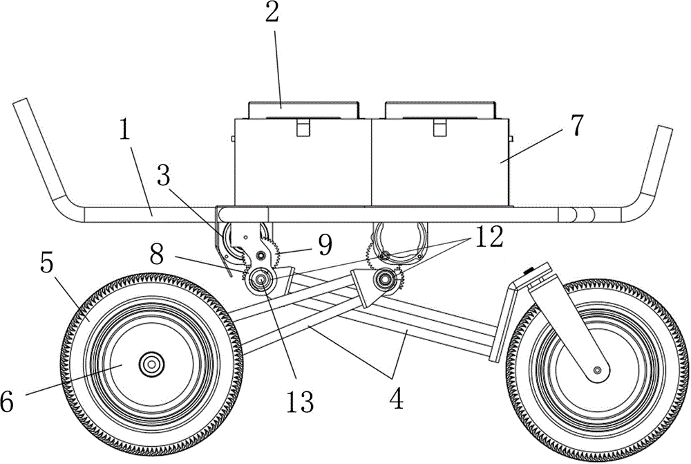
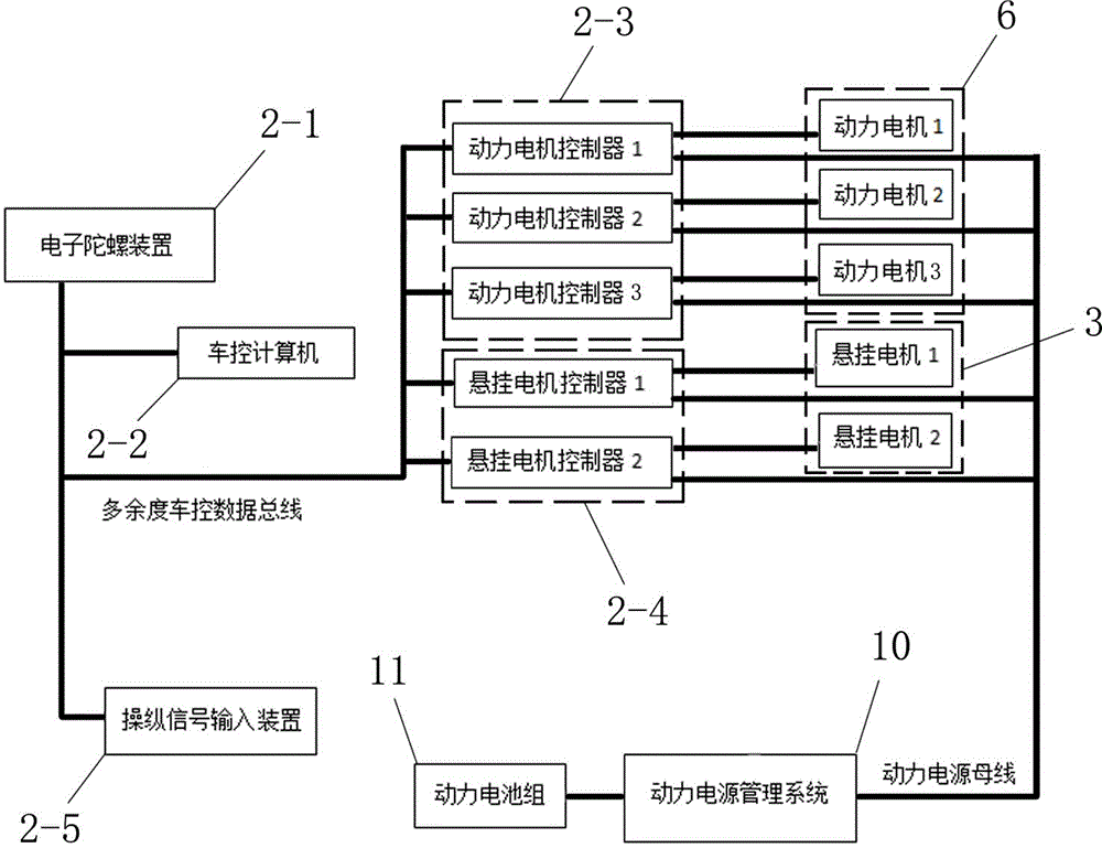
[0021] Such as figure 1 As shown, an electric vehicle chassis with a suspension frame 1 includes a frame 1, and the frame 1 is equipped with several groups of independent walking devices; the running device includes a control system 2, a suspension motor 3, a cantilever 4, Wheel 5 and power motor 6; the top of the vehicle frame 1 is provided with a housing frame 7, and the control system 2 is placed in the housing frame 7; the bottom of the vehicle frame 1 is provided with a cantilever shaft fixing frame 8, and the cantilever shaft is fixed The frame 8 is connected to the cantilever shaft 13 in the horizontal direction through the longitudinal rotation bearing 12. The upper end of the cantilever 4 is connected to the cantilever shaft 13. The cantilever shaft 13 is connected to the output shaft of the suspension motor 3 through the transmission gear set 9. The...


PUM


Abstract

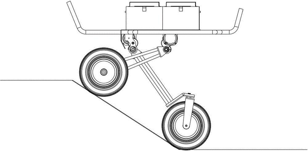
The invention discloses a chassis structure of a suspension frame electric vehicle. The chassis structure comprises a frame. The frame is provided with a plurality of sets of independent walking devices. Each walking device comprises a control system, a hanging motor, a cantilever, wheels and a power motor, and a containing frame is arranged on the top of the frame. The control systems are arranged in the containing frame. A cantilever shaft fixing frame is arranged at the bottom of the frame and connected with cantilever shafts in the horizontal direction through longitudinal rotating bearings. The upper ends of the cantilevers are connected with the cantilever shafts. The cantilever shafts are connected with output shafts of the hanging motors through transmission gear sets. The lower ends of the cantilevers are connected with the wheels. The power motors are hub type power motors installed on the wheels. Compared with the prior art, the chassis structure has the advantages that during driving, the wheels can be automatically lifted up or placed down through a vehicle chassis when the ground is bumped or oblique, and the wheels are kept to make contact with the ground; the vehicle body part is kept horizontal constantly, and the gravity center is in the safety range all the time.

Description

technical field [0001] The invention relates to an electric vehicle chassis, in particular to a chassis structure of an electric vehicle with a suspension frame. Background technique [0002] The suspension method adopted by the existing automobile chassis cannot actively and quickly change the suspension height. When the inclination of the road surface changes, the inclination angle of the vehicle body will inevitably be changed, thereby reducing the stability or even overturning. And the front and rear wheel bases are reduced, which makes the vehicle easy to overturn in the horizontal and vertical directions; this feature limits the driving capacity and carrying capacity of the vehicle on complex terrain, making it only suitable for use on roads, and only for people to walk. There is no ideal way of maneuvering on terrains such as walking paths and field ridges. [0003] Existing bionic walking robots use a very complex multi-degree-of-freedom hydraulic drive method. This...

Claims


Application Information

Patent Timeline
IPC IPC(8): B62D11/04B60G17/0165
Inventor 郑和邹帆
Owner 邹帆
Learn More