
Cardan universal joint type flap transmission mechanism

A cross universal joint and transmission mechanism technology, which is applied in the direction of aircraft transmission, aircraft power transmission, aircraft power device, etc., can solve the problems of reduced transmission accuracy and long transmission path of aileron, and achieve large variation range and symmetrical deflection Good degree and good synchronization effect

Inactive Publication Date: 2015-10-14
JIANGXI HONGDU AVIATION IND GRP
View PDF7 Cites 1 Cited by
  • Summary
  • Abstract
  • Description
  • Claims
  • Application Information

AI Technical Summary

Problems solved by technology

For wings with large aspect ratios, the requirements for the control torque of the body roll are getting higher and higher. The traditional ailerons arranged at the root of the wing can no longer meet the requirements. In order to meet the necessary control torque of the body roll, while maximizing To reduce the working load of the steering gear, the ailerons of the target drone need to be arranged at the end of the wings. Although this overall layout reduces the difficulty of controlling the body, it leads to a long transmission path of the ailerons and a decrease in transmission accuracy.
At present, the ailerons of aircraft are widely used in the form of electric transmission, hydraulic control circuit or multiple sets of linkage mechanisms in series and parallel. However, the wings of target aircraft are generally thin, so the application of the transmission form of aircraft ailerons on the ailerons of target aircraft has certain advantages. limitation

Method used


Image

  • Cardan universal joint type flap transmission mechanism
  • Cardan universal joint type flap transmission mechanism
  • Cardan universal joint type flap transmission mechanism

Examples


Embodiment Construction

[0017] The present invention will be further described below in conjunction with the accompanying drawings and specific embodiments. The following examples are only used to illustrate the present invention, and are not intended to limit the protection scope of the present invention.

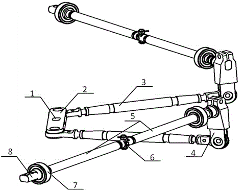
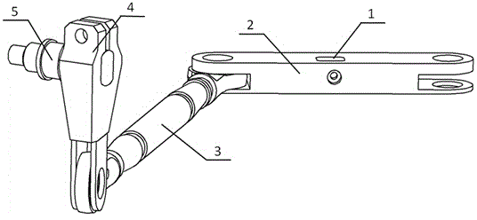
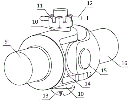
[0018] figure 1 As shown, a cross universal joint type aileron transmission mechanism of the present invention, the set of aileron transmission mechanism includes a rotating block 2, a connecting rod 3, a rocker arm 4, a transmission shaft 5, a cross universal joint assembly 6 and a rolling bearing 7 , the two ends of the rotating block 2 are respectively hinged with the connecting rod 3, the connecting rod 3 is hinged with one end of the rocker arm 4, the other end of the rocker arm 4 is connected with the transmission shaft 5, and the rolling bearing 7 is installed on both ends of the transmission shaft 5 with interference fit, and the transmission shaft 5 Split into two sections of connection...


PUM


Abstract

The invention discloses a cardan universal joint type flap transmission mechanism. The cardan universal joint type flap transmission mechanism comprises a rotary block, connecting rods, swing arms, transmission rotary shafts, cardan universal joint assemblies and rolling bearings. The two ends of the rotary block are hinged to the connecting rods respectively. The connecting rods are hinged to one ends of the swing arms. The other ends of the swing arms are connected with the transmission rotary shafts. The rolling bearings are installed at the two ends of the transmission rotary shafts in an interference fit mode. The transmission rotary shafts are split into two sections for connection according to requirements through the cardan universal joint assemblies. The mechanism can effectively solve the problem that transmission accuracy is affected by small wing space, the long transmission path and wing bending deformation, can be widely applied to occasions with limited installation space and long-distance transmission, and is driven by a single power source, motion synchronism of a left flap and a right flap is good, the deflection symmetry of the flaps in the forward direction and the reverse direction is good, and response is reliable. Through refitting, the mechanism can be universal in design according to different types and different airload conditions.

Description

technical field [0001] The invention relates to an aileron transmission mechanism, in particular to a cross universal joint type aileron transmission mechanism. Background technique [0002] With the advancement of science and technology, more and more target drones use large aspect ratio wings to increase the endurance time and range, and improve the performance of the target drone. For wings with large aspect ratios, the requirements for the control torque of the body roll are getting higher and higher. The traditional ailerons arranged at the root of the wing can no longer meet the requirements. In order to meet the necessary control torque for the body roll, while maximally To reduce the working load of the steering gear, the ailerons of the target drone need to be arranged at the end of the wings. Although this overall layout reduces the difficulty of controlling the body, it leads to a long transmission path of the ailerons and a decrease in transmission accuracy. At ...

Claims


Application Information

Patent Timeline
IPC IPC(8): B64C13/30
Inventor 洪厚全付俊兴陈雷李雁飞王再玉皇东亚陈龙朱照阳
Owner JIANGXI HONGDU AVIATION IND GRP
Learn More