Exhaust gas turbocharger

A technology of exhaust gas turbine and supercharger, which is applied to gas turbine devices, jet propulsion devices, machines/engines, etc., and can solve problems affecting the function of exhaust gas turbochargers, etc.

Inactive Publication Date: 2015-10-14
BOSCH MAHLE TURBO SYST GMBH & CO KG
View PDF7 Cites 1 Cited by
  • Summary
  • Abstract
  • Description
  • Claims
  • Application Information

AI Technical Summary

Problems solved by technology

In exhaust gas turbochargers, however, whose rotors are installed in the turbine housing as well as in the compressor housing, without a bearing housing being arranged between these two housings, undesired heat transfer can occur, which under certain conditions can cause the function of the exhaust gas turbocharger to be affected

Method used


Image

  • Exhaust gas turbocharger
  • Exhaust gas turbocharger
  • Exhaust gas turbocharger

Examples


Embodiment Construction

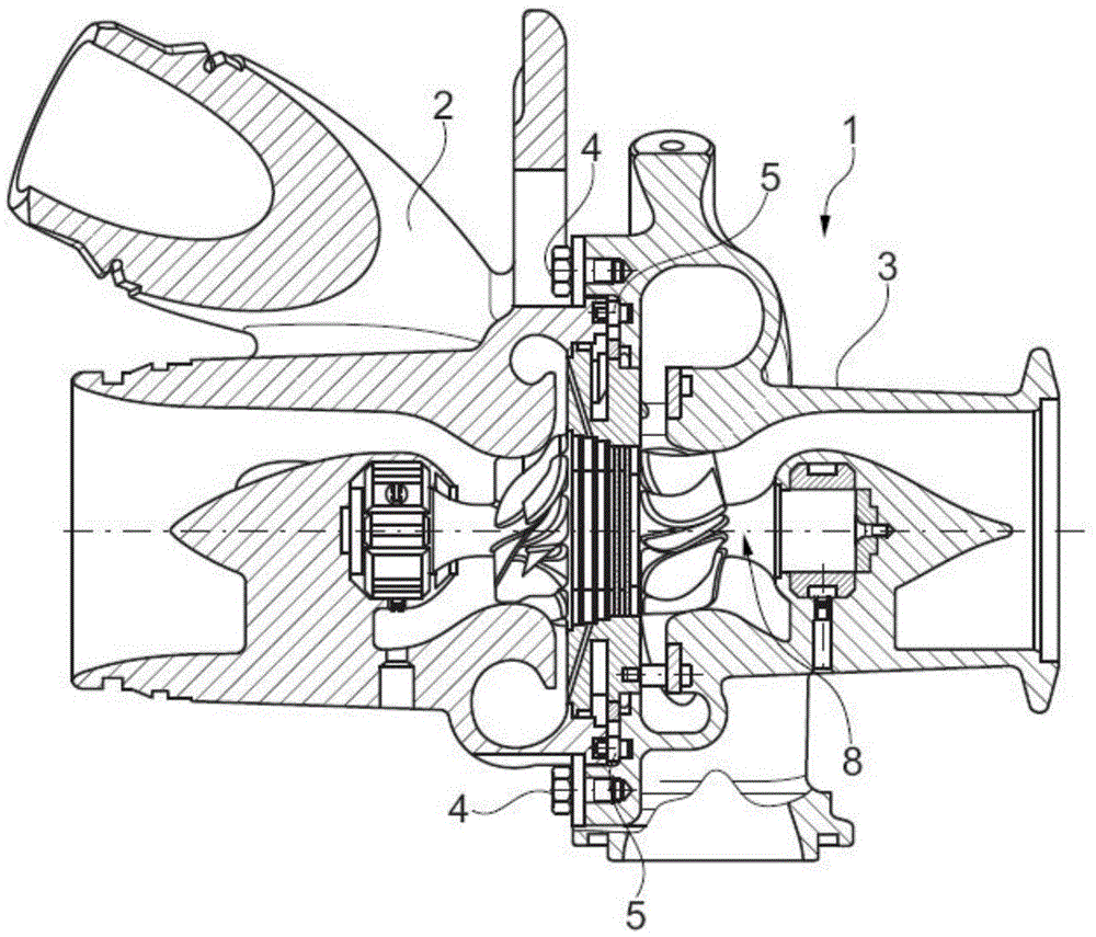
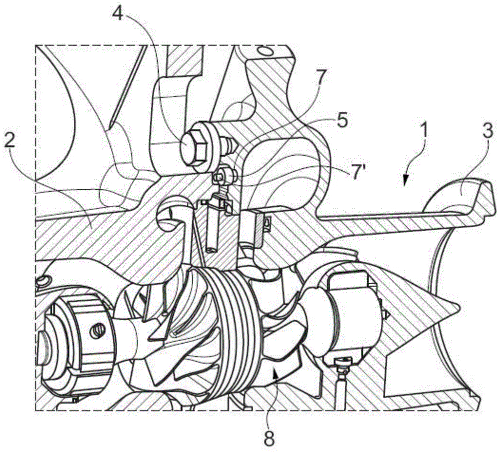
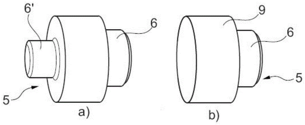
[0022] according to figure 1 , figure 2 and Figure 7 , the exhaust gas turbocharger 1 according to the invention comprises a compressor housing 2 and a turbine housing 3 . The compressor housing 2 is in this case screwed to the turbine housing 3 via bolts 4 . According to the invention, the turbine housing 3 is now connected to the compressor housing 2 via at least three insulating spacer pins 5 . Obviously, four or more spacer pins 5 can also be provided here. According to the invention, these spacer pins 5 are formed of a thermally insulating material, such as ceramic, especially zirconia, with the result that at least the heat transfer between the relatively hot turbine housing 3 and compressor housing 2 is minimized. For the illustrated embodiment of the exhaust gas turbocharger 1 according to the invention, the bearing housing normally arranged between the compressor housing 2 and the turbine housing 3 has been omitted, so that the two housing parts 2 , 3 are mutual...


PUM


Abstract

An exhaust gas turbocharger may include a compressor housing and a turbine housing. The turbine housing may be connected to the compressor housing via a plurality of spacer pins composed of a heat-insulating material. The plurality of spacer pins may respectively include a head and at least one axial pin.

Description

technical field [0001] The invention relates to an exhaust gas turbocharger with a compressor housing and a turbine housing according to the preamble of claim 1 . Background technique [0002] A universal exhaust gas turbocharger is known from DE 10 2008 048 126 A1 with a compressor housing and a turbine housing, wherein the bearings of the rotor are accommodated in the turbine housing and in the compressor housing because they are directly attached to each other , without the bearing housing that is usually arranged between the turbine housing and the compressor housing. The turbine housing is in this case connected to the turbine housing via a spacer ring, wherein the spacer ring simultaneously serves as a bearing ring for the variable turbine geometry. Radially outside the spacer ring, the turbine housing is also directly connected to the compressor housing, with the result that heat transfer can take place here. [0003] An exhaust gas turbocharger is also known from D...

Claims


Application Information

Patent Timeline
Patent Type & Authority Applications(China)
IPC IPC(8): F02C6/12F02C7/20
CPCF02C7/24F02C6/12F05D2220/40F05D2230/642F05D2260/231F05D2260/30F01D25/16F05D2300/5024F01D25/246
Inventor 马哈尔·克卢萨切克
Owner BOSCH MAHLE TURBO SYST GMBH & CO KG
Why Eureka
Try Eureka