Method for utilizing infrared thermal imaging technology to detect floor heating pipe

A technology of infrared thermal imaging and infrared thermal imaging camera, which is used in pipeline systems, mechanical equipment, gas/liquid distribution and storage, etc. Detecting the effect of difficulty

Inactive Publication Date: 2015-10-14
XIAN UNIV OF TECH
View PDF5 Cites 6 Cited by
  • Summary
  • Abstract
  • Description
  • Claims
  • Application Information

AI Technical Summary

Problems solved by technology

[0004] The purpose of the present invention is to provide a method for detecting geothermal pipelines using infrared thermal imaging technology, which solves the problem that the existing geothermal pipelines cannot be quickly and non-destructively detected

Method used


Image

  • Method for utilizing infrared thermal imaging technology to detect floor heating pipe
  • Method for utilizing infrared thermal imaging technology to detect floor heating pipe

Examples


Embodiment 1

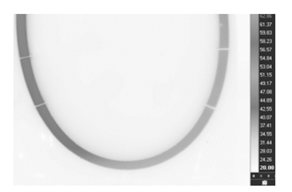
[0023] Turn on the SC7000 infrared thermal imager and perform preheating treatment: place it for 15 minutes until the sound of the internal pump becomes smaller until it disappears and the image is stable, and it is connected to the computer; open the floor heating valve, adjust the pipeline test parameters, and control the water temperature to 50℃, water velocity is 0.05m 3 / h, make hot water flow into the floor heating pipe and preheat for 4 hours, place the infrared thermal imaging camera in a corner of the room, use the infrared thermal imaging camera supporting software FLIR Altair to calibrate the room coordinates, and record the video at the angle of the lens perpendicular to the floor, The distance between the lens and the floor is 30cm, and it moves along the floor plane in a row scanning manner until it moves to the opposite side of the room to save the video content. Use the supporting software of the infrared thermal imager to synthesize the pipeline layout diagram...

Embodiment 2

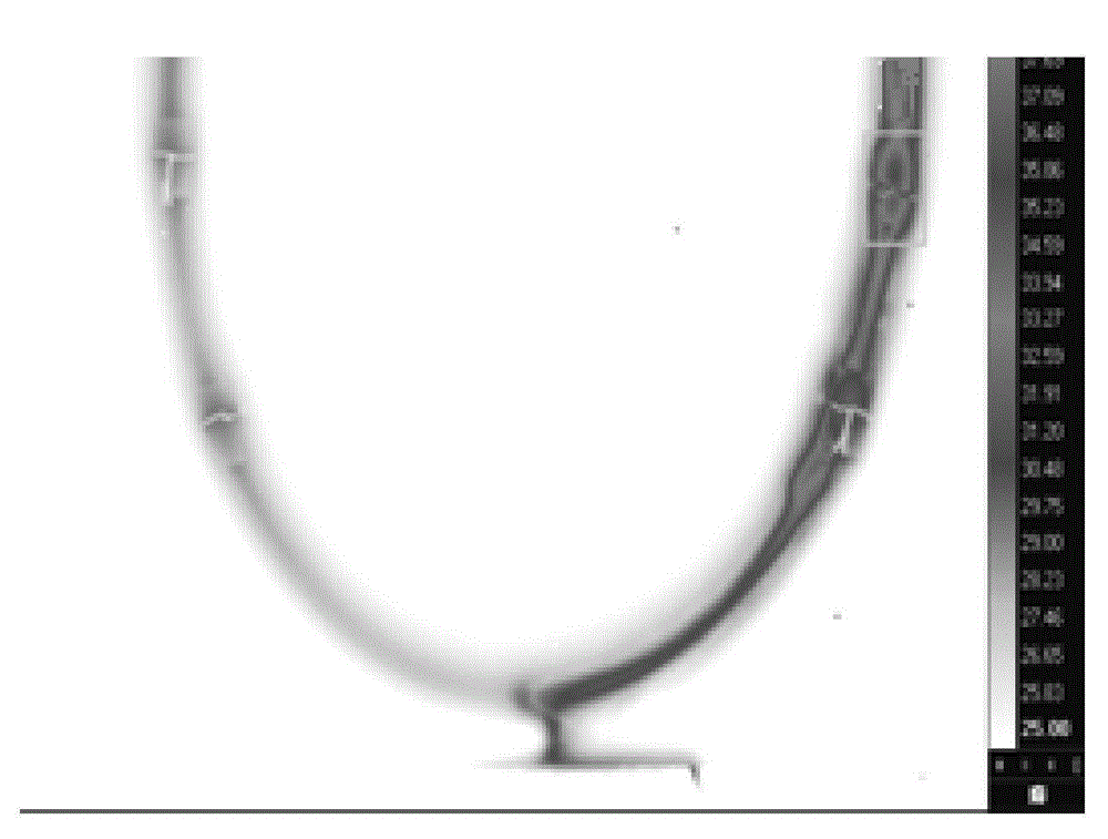
[0025] Turn on the SC7000 infrared thermal imager and perform preheating treatment: place it for 17 minutes until the sound of the internal pump becomes smaller until it disappears and the image is stable, and it is connected to the computer; open the floor heating valve, adjust the pipeline test parameters, and control the water temperature to 55℃, water velocity is 0.07m 3 / h, make hot water flow into the floor heating pipe and preheat for 4.5 hours, place the infrared thermal imaging camera in a corner of the room, use the infrared thermal imaging camera supporting software FLIR Altair to calibrate the room coordinates, and record the video at the angle of the lens perpendicular to the floor, The distance between the lens and the floor is 40cm, and it moves along the floor plane in a row scanning manner until it moves to the opposite side of the room to save the video content. Use the supporting software of the infrared thermal imager to synthesize the pipeline layout diagr...

Embodiment 3

[0027] Turn on the SC7000 infrared thermal imager and perform preheating treatment: place it for 20 minutes until the sound of the internal pump becomes smaller until it disappears and the image is stable, and it is connected to the computer; open the floor heating valve, adjust the pipeline test parameters, and control the water temperature to 60℃, water velocity is 0.1m 3 / h, make hot water flow into the floor heating pipe and preheat for 5 hours, place the infrared thermal imaging camera in a corner of the room, use the infrared thermal imaging camera supporting software FLIR Altair to calibrate the room coordinates, and record the video at the angle of the lens perpendicular to the floor, The distance between the lens and the floor is 50cm, and it moves along the floor plane in a row scanning manner until it moves to the opposite side of the room to save the video content. Use the supporting software of the infrared thermal imager to synthesize the pipeline layout diagram ...


PUM


Abstract

The invention discloses a method for utilizing an infrared thermal imaging technology to detect a floor heating pipe. The method comprises the following steps: starting an infrared thermal imager to perform preheating treatment; adjusting pipe measuring parameters, placing the infrared thermal imager at one corner of a room, utilizing infrared thermal imager matching software to perform room coordinate calibration, performing recording at an angle with a lens perpendicular to the floor, moving along the plane of the floor in a scanning mode until moving to the opposite side of the room, and saving the content of the video; synthesizing a room pipe laying graph, analyzing and comparing images, finding the location of a pipe with the color obviously different from that of other pipes, and accordingly determining the pipe leakage location, namely finishing the detection of the floor heating pipe. The method can quickly detect the pipe leakage location; besides, the detection method is in a non-destructive detection mode, greatly reduces detection difficulty and does not need to destroy the floor, and accordingly the detection cost is reduced.

Description

technical field [0001] The invention belongs to the technical field of non-destructive testing, and in particular relates to a method for detecting geothermal pipelines using infrared thermal imaging technology. Background technique [0002] The heating method in the current society is mainly based on underground water heating pipes. Floor heating pipes use ground radiation to dissipate heat. . Floor heating mainly uses the heat storage of the ground itself and the law of heat radiation upwards to conduct from bottom to top to achieve the purpose of heating. At present, floor heating pipes mostly use high-temperature resistant non-cross-linked polyethylene (called PE-RT pipe) materials, and rarely use metal pipes. This is because the former has incomparable advantages, not only corrosion resistance, aging resistance, and low water resistance. Moreover, it has good flexibility, the bending part relaxes quickly, does not appear "rebound" phenomenon, has good low temperature ...

Claims


Application Information

Patent Timeline
Patent Type & Authority Applications(China)
IPC IPC(8): F17D5/02
Inventor 陈文革马佳吴诗勤
Owner XIAN UNIV OF TECH
Why Eureka
Try Eureka