
MEMS device capacitance detection method

A technology for capacitance detection and devices, which is applied in the field of micro-electromechanical systems, can solve the problems of increased noise in low-frequency bands and low reliability of detection signals.

Inactive Publication Date: 2015-10-14
ACUTI MICROSYST
View PDF6 Cites 7 Cited by
  • Summary
  • Abstract
  • Description
  • Claims
  • Application Information

AI Technical Summary

Problems solved by technology

However, in the case of equal-frequency drive, the detected signal is equal to the driving frequency, and at the same time, the same-frequency driving signal interferes with the detection signal, and the reliability of the detection signal will be very low.
Similarly, if the half-frequency drive is used, although the electrical signal coupling caused by the conventional resonant frequency drive is suppressed, this method will still modulate the 1 / f noise in the low-frequency band to the half-frequency of the resonant frequency, making the low-frequency band increased noise

Method used


Image

  • MEMS device capacitance detection method
  • MEMS device capacitance detection method
  • MEMS device capacitance detection method

Examples


Embodiment Construction

[0034] The following will clearly and completely describe the technical solutions in the embodiments of the present invention in combination with specific applications of the present invention. Obviously, the described embodiments are only some of the embodiments of the present invention, not all of them. Based on the embodiments of the present invention, all other embodiments obtained by persons of ordinary skill in the art without making creative efforts belong to the protection scope of the present invention.

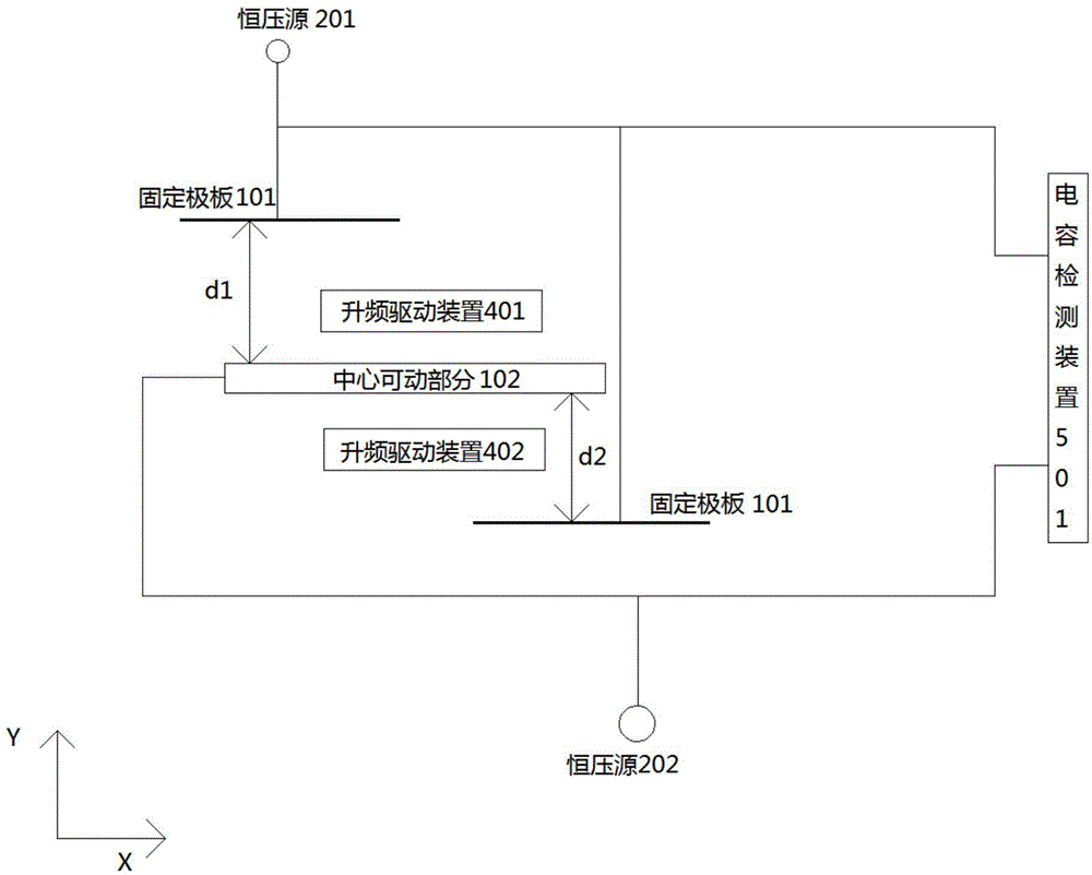
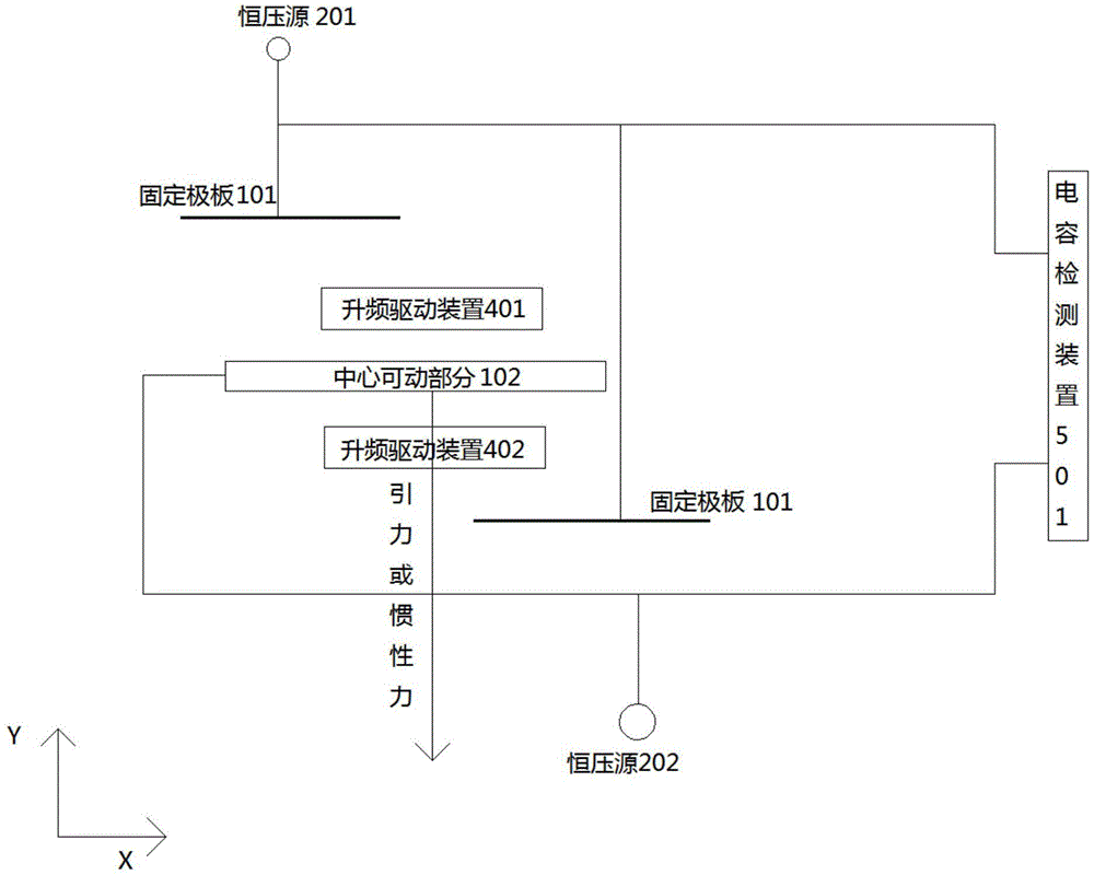
[0035] Such as figure 1As shown, the variable capacitor is composed of two fixed plates 101 and a central movable part 102 . The fixed pole plate is parallel to the X axis, and its normal direction is parallel to the Y axis. The central movable part 102 is parallel to the fixed pole plate, and its normal direction is parallel to the Y axis. The distance between the central movable part and the left fixed pole plate in the figure in the Y-axis direction is denoted a...


PUM


Abstract

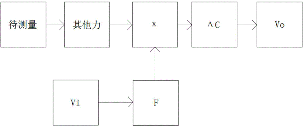
The invention discloses an MEMS device capacitance detection method which comprises the following steps: one or more variable capacitors are provided, wherein each variable capacitor comprises two parallel fixation pole plates and a center movable part arranged between the two fixation pole plates, the center movable part being parallel to the fixation pole plates, the fixation pole plates being parallel to the X axis, the normal direction of each fixation pole plate being parallel to the Y axis, and the normal direction of the center movable part being parallel to the Y axis; one or more variable capacitors in the variable capacitors have periodical change due to the driving of electrostatic force, wherein the electrostatic force is generated by a frequency-rising driving method, the center movable part can move in the X axis and / or Y axis direction; and capacitance change of one or more variable capacitors in the variable capacitors can be detected by utilizing a DC voltage offset detection method. According to the method, by combining the frequency-rising driving and the DC detection, the frequency-rising driving separates a driving voltage (high frequency) and a signal voltage (low frequency) in the frequency domain, thereby greatly reducing interference of the driving signal on the detection signals.

Description

technical field [0001] The invention relates to the field of microelectromechanical systems, in particular to a method for detecting the capacitance of a MEMS device. Background technique [0002] Micro-electro-mechanical system (MEMS micro-electro-mechanical system) devices have the characteristics of small size, long life, low energy consumption, easy integration and low cost, so they have been widely used in industry, information, aerospace, defense and other fields. [0003] According to different detection methods, MEMS devices can be divided into piezoresistive, piezoelectric, capacitive, thermocouple, optical fiber, electromagnetic, resonant, etc. Among them, piezoresistive, piezoelectric and capacitive are the current The mainstream direction, and capacitive MEMS devices have been the most widely used due to their outstanding advantages such as large measurement range, high sensitivity, fast dynamic response, and good stability, and have become the research focus of ...

Claims


Application Information

Patent Timeline
IPC IPC(8): G01R27/26
Inventor 杨少军万蔡辛蔡闹闹
Owner ACUTI MICROSYST
Learn More