Contactless contactor with auxiliary contact

A non-contact contactor and auxiliary contact technology, applied in relays, relay ventilation/cooling/heating, electrical components, etc., can solve problems such as power loss, burned motor coils, contact ablation, etc., to improve service life , to ensure the cooling effect, to avoid the effect of false triggering

Active Publication Date: 2015-10-14
商晓 +1
View PDF6 Cites 4 Cited by
  • Summary
  • Abstract
  • Description
  • Claims
  • Application Information

AI Technical Summary

Problems solved by technology

[0003] (1) Ordinary electromagnetic AC contactor: there is power loss during use, and when the coil is running, there is noise, and the noise is louder when the armature has dirt
When the load current is large, it is easy to burn the contacts so that the contacts cannot be released in time
When the main electronic contact is loaded and released, it is easy to generate arc ignition, which will ablate the contact and cause poor contact. In serious cases, it may cause a phase loss of the power supply and burn the motor coil
In frequent switching applications, it is more likely to be damaged
The service life is short, and the control coil consumes a lot of energy, which is more obvious when the power is high
(2) Ordinary solid state relays: The biggest d

Method used


Image

  • Contactless contactor with auxiliary contact
  • Contactless contactor with auxiliary contact
  • Contactless contactor with auxiliary contact

Examples


Embodiment 1

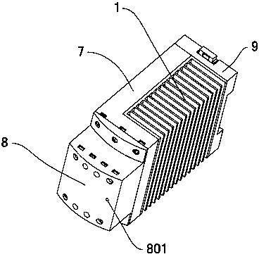
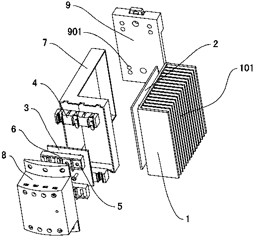
[0060] Refer to attached Figure 1~2 , the non-contact contactor with auxiliary contacts includes a radiator 1, a main circuit board 2, an auxiliary circuit board 3, a main terminal 4, an auxiliary terminal 6, a main circuit housing 7, an auxiliary circuit housing 8 and a fixing plate 9. The inner side of the vertical part of the L-shaped main circuit housing 7 and the front side of the horizontal part are open, the main circuit board 2 is placed in the vertical part of the main circuit housing 7, the main terminal 4 is fixed on the front end of the radiator 1, and placed side by side In the horizontal part of the main circuit housing 7, it is connected with the main circuit board 2 by wires, and the thyristor element 201 of the main circuit board 2 ( Figure 4 ) is fixed on the side of the radiator 1, and the other side of the radiator 1 is provided with multiple vertical cooling fins 101. The side surfaces are all arranged on the same plane as the corresponding side surface...

Embodiment 2

[0086] refer to Figure 15 The difference between this embodiment and Embodiment 1 is that the main circuit housing 7 is T-shaped, the main circuit board 2 is placed in the vertical part of the main circuit housing 7, and the two sides of the vertical part of the main circuit housing 7 are respectively provided with radiators 1 , can cool both sides of the main circuit board 2 at the same time, and the components on the main circuit board 2 can be arranged on both sides of the substrate, further improving the heat dissipation effect and adapting to frequent switching. Other structures are with embodiment 1.

[0087] refer to Figure 16 The difference between this embodiment and Embodiment 1 is that in the three-phase non-contact contactor module, the bidirectional thyristor T1 is realized through the parallel connection of thyristors T4 and T7, the bidirectional thyristor T2 is realized through the parallel connection of thyristors T5 and T8, and the bidirectional thyristor T...

Embodiment 3

[0089] refer to Figure 17 , the main circuit board 2 (not visible in this figure) is fixed on the front side of the radiator 1, and the radiator 1 is provided with cooling fins 101 extending to the rear. The main circuit housing 7 is fixed in front of the radiator 1 and covers Located on the outside of the main circuit board 2, preferably an auxiliary circuit board 3 can also be fixed at the front end of the main circuit board 2, the auxiliary circuit housing 8 is fixed on the front side of the main circuit housing 7 and is covered on the outside of the auxiliary circuit board 3. Other structures are with embodiment 1.

[0090] refer to Figure 18 The difference between this embodiment and Embodiment 1 is that the protection circuit composed of the resistor R7 and the capacitor C4, the resistor R8 and the capacitor C5, and the resistor R9 and the capacitor C6 respectively connected in parallel at both ends of the triacs T1 to T3 is omitted. Other circuit structures are the ...


PUM


Abstract

A contactless contactor with an auxiliary contact belongs to the field of electrical components. The contactless contactor comprises a housing, a heat radiator, a main circuit board, a main terminal and a control signal terminal. The contactless contactor is characterized in that the housing comprises a main circuit housing and an auxiliary circuit housing which is fixed in front of the main circuit housing; an auxiliary circuit board and an auxiliary terminal are fixed in the auxiliary circuit housing; the main circuit board is provided with a control signal input module and a main circuit module; the control signal input module is connected with the control signal input end of the main circuit module; the auxiliary circuit board is provided with an auxiliary contact module; the driving signal of the auxiliary contact module is from the output end of two random main electronic contacts of the main circuit module, and the auxiliary contact module becomes a real auxiliary contact. The contactless contactor with the auxiliary contact has functions of settling a problem that the auxiliary contact for matching is necessary at an electrical interlock occasion with the contactless contactor, preventing auxiliary contact false triggering which may be caused in a prior-art product in which the auxiliary contact is triggered by a control signal, and ensuring high safety in use.

Description

technical field [0001] A non-contact contactor with auxiliary contacts belongs to the field of electrical components. Background technique [0002] At present, there are three main types of devices used as electrical switches in industrial sites: ordinary electromagnetic AC contactors, ordinary solid-state relays, and ordinary non-contact contactors. The above three devices have the following deficiencies in specific use: [0003] (1) Ordinary electromagnetic AC contactor: there is power loss during use, and when the coil is running, there is noise, and the noise is louder when the armature has dirt. When the load current is large, it is easy to burn the contacts so that the contacts cannot be released in time. When the main electronic contact is loaded and released, it is easy to generate arc ignition, which will ablate the contact and cause poor contact. In serious cases, it will cause a phase loss of the power supply and burn the motor coil. In applications with frequen...

Claims


Application Information

Patent Timeline
IPC IPC(8): H01H45/04H01H45/12H01H45/14H01H47/02
Inventor 商晓陶祥军
Owner 商晓
Why Eureka
Try Eureka