Passive high-voltage direct-current circuit breaker and implementation method therefor

A high-voltage direct current and circuit breaker technology, applied in high-voltage/high-current switches, circuits, circuit devices, etc., can solve the problems that the breaking time cannot meet the requirements of multi-terminal flexible direct current transmission systems, high manufacturing costs, and high technical difficulty, so as to shorten the operation The effect of time, low equipment cost and mature technology

Active Publication Date: 2015-10-14
STATE GRID CORP OF CHINA +2
View PDF6 Cites 33 Cited by
  • Summary
  • Abstract
  • Description
  • Claims
  • Application Information

AI Technical Summary

Problems solved by technology

[0003] There are usually three ways to break the DC current. One is to add an auxiliary circuit on the basis of the conventional AC mechanical circuit breaker to superimpose the increased oscillation current on the DC current of the breaking arc gap, and use the current to break when the current crosses zero. The mechanical circuit breaker manufactured using this principle cannot meet the requirements of the multi-terminal flexible DC transmission system in terms of breaking time; one is to use high power to turn off power electronic devices and directly break the DC current, using this principle Although the manufactured solid-state circuit breaker can meet the requirements of the multi-terminal flexible DC system in terms of time, the loss is

Method used


Image

  • Passive high-voltage direct-current circuit breaker and implementation method therefor
  • Passive high-voltage direct-current circuit breaker and implementation method therefor
  • Passive high-voltage direct-current circuit breaker and implementation method therefor

Examples


Embodiment Construction

[0044] The specific implementation manners of the present invention will be further described in detail below in conjunction with the accompanying drawings.

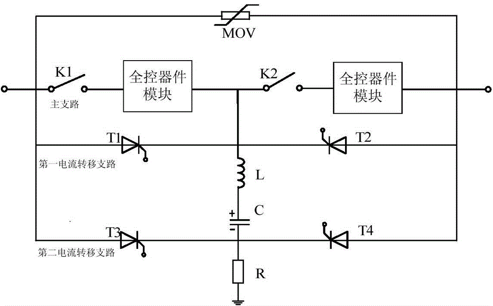
[0045] The topological structure diagram of the passive high-voltage DC circuit breaker provided by the present invention is as follows figure 1 As shown, the high-voltage DC circuit breaker is connected in series to the DC system through ports 1 and 2, including a parallel energy absorption branch, a main branch and a current transfer branch. The current transfer branch includes the first current transfer branch and the first current transfer branch. The second current transfer branch; the energy absorption branch is composed of non-linear resistors; the high-voltage DC circuit breaker is connected in series in the DC system, and the main branch includes at least two sets of high-speed mechanical switches and at least two sets of full control in series device module. Two sets of high-speed mechanical switches are denot...


PUM


Abstract

A passive high-voltage direct-current circuit breaker and an implementation method therefor. The high-voltage direct-current circuit breaker is connected in a direct-current system in series, and comprises an energy absorption branch, a main branch and a current transfer branch which are connected in parallel, wherein the current transfer branch comprises first current transfer branches (T1, T2) and second current transfer branches(T3, T4); the energy absorption branch is composed of a nonlinear resistor (MOV); and the main branch comprises at least two groups of high-speed mechanical switches (K1, K2) and at least two groups of full controlled device modules which are connected in series. Since the circuit has a simple topology structure, is simple and convenient to control, and is flexible to apply, the energy required by injecting a current into a capacitor can be obtained from a system without configuring an auxiliary power source, thereby improving the reliability of an apparatus. The used power electronic devices are mainly half controlled thyristors, so that the series connection technology is mature, the capability for current segmentation is strong, the level of withstand voltage is high, the expansion capability is strong, and the costs of devices are low.

Description

technical field [0001] The invention relates to a DC circuit breaker, in particular to a passive high-voltage DC circuit breaker and its realization method. Background technique [0002] With the application of multi-terminal flexible DC and DC grid technology based on voltage source converter (VSC), fast DC circuit breakers have become one of the key equipment to ensure the stable, safe and reliable operation of the system. In the AC system, the AC current has two natural zero-crossing points in one cycle, and the AC circuit breaker uses the natural zero-crossing points of the current to cut off the current, while in the DC system, the DC current does not have a natural zero-crossing point, so the DC current The breaking of the current is much more difficult than the breaking of the alternating current. [0003] There are usually three ways to break the DC current. One is to add an auxiliary circuit on the basis of the conventional AC mechanical circuit breaker to superimp...

Claims


Application Information

Patent Timeline
IPC IPC(8): H02H3/087
CPCH02H3/087H01H33/596
Inventor 周万迪魏晓光高冲贺之渊张升
Owner STATE GRID CORP OF CHINA
Why Eureka
Try Eureka