Permanent magnetic power generator

A permanent magnet energy and power machine technology, applied in the direction of generators/motors, electromechanical devices, electrical components, etc., can solve the problems of heavy environmental pollution and insufficient energy demand, and achieve the effect of low operating cost, no pollution, and clean energy

Inactive Publication Date: 2015-10-14
潘家烺
View PDF0 Cites 1 Cited by
  • Summary
  • Abstract
  • Description
  • Claims
  • Application Information

AI Technical Summary

Problems solved by technology

[0004] The purpose of the invention of the present invention is to solve the problems of heavy environmental pollution and insufficient energy demand of fuel oil, gas engines and steam engines in the prior art, to provide a fuel-free, non-polluting environment, low operating cost, and no need to provide or supplement other energy sources. Permanent magnetic energy magnetic power machine with a wide range of applications, stable operation, and constant output of continuous power without complex control or maintenance systems

Method used


Image

  • Permanent magnetic power generator
  • Permanent magnetic power generator
  • Permanent magnetic power generator

Examples


Embodiment Construction

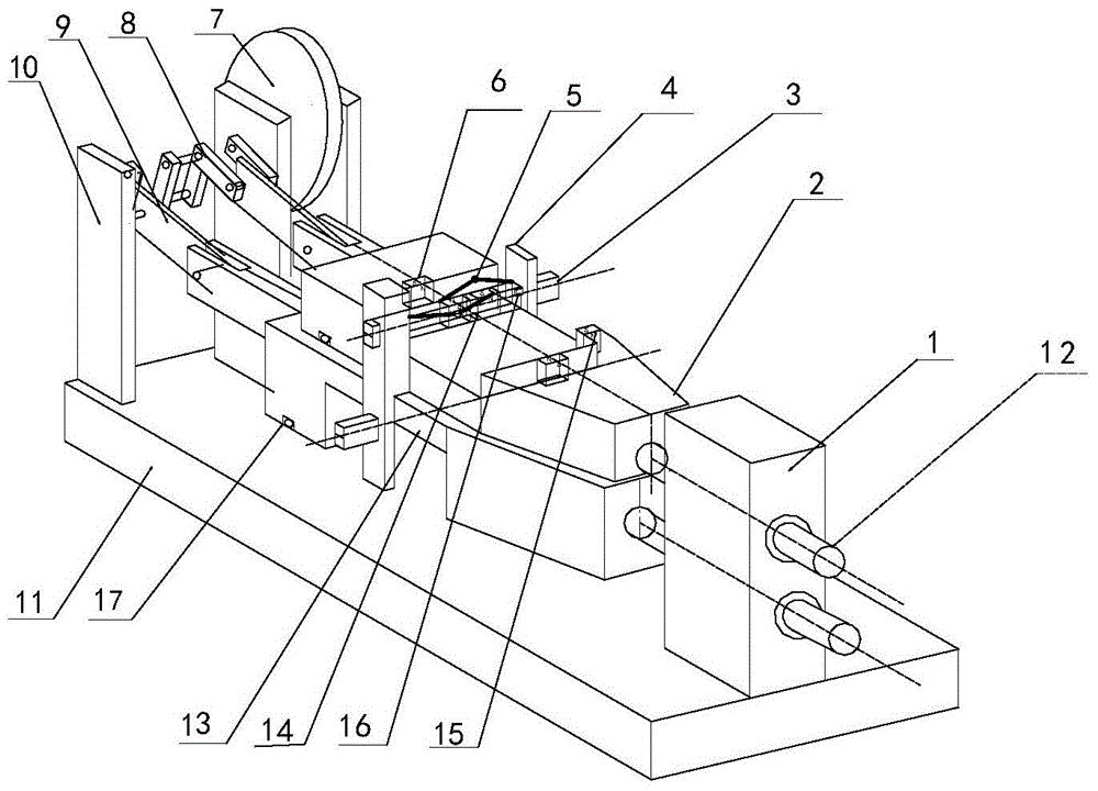
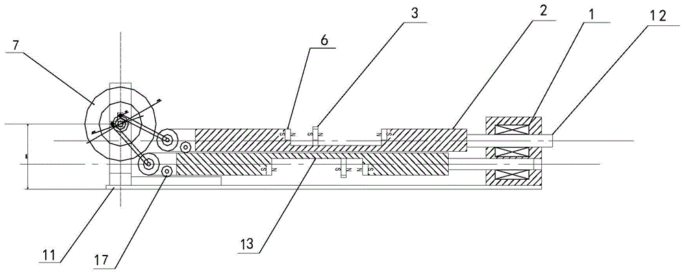
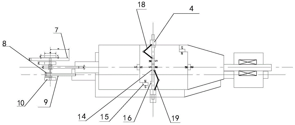
[0017] refer to Figure 1-Figure 3 . In a preferred embodiment described below, the permanent magnet energy magnetic power machine has two magnetic sliders 2 with concave grooves, and the two magnetic sliders 2 are arranged back to back and parallel up and down. The two ends of the base 11 are fixedly connected with the bearing support 1 and the flywheel support 10 respectively, and the magnetic slider 2 is connected with the power output flywheel 7 through the crankshaft mechanism 8 . The bottom planes of the two magnetic sliders 2 can be equipped with pulleys 17 . Wherein, one end of the two magnetic sliders 2 is installed in the linear sliding bearing of the linear bearing support 1 through the connecting shaft 12 , and the other end is connected to the crank mechanism of the power output flywheel 7 through the crank connecting rod 9 . There is an opening groove 13 in the middle of the magnetic slider 2 , and a permanent magnetic energy magnetic block 6 is respectively in...


PUM


Abstract

The invention provides a permanent magnetic power generator and aims to provide a magnetic power generator which can constantly output a continuous power without supplying or supplementing of other energies. The permanent magnetic power generator is realized through a technical solution which is characterized in that two magnetic slide blocks are provided with an open recessed trough; permanent magnetic blocks which are symmetrical with each other are inlaid at the front-side straight wall and the back-side straight wall of the open recessed trough; the two magnetic slide blocks are arranged vertically in the vertical direction in a back-to-back manner; one end of each of the two magnetic slide blocks is slidably connected with a bearing support at one end of the base through a connecting shaft, and the other end is connected with a crankshaft mechanism of a flywheel support at the other end of the base through a crankshaft connecting rod; the open recessed trough of the two magnetic slide blocks is internally provided with a slide block direct changing mechanism which is fixed through vertical column supports at two sides and slides; the slide block direction changing mechanism comprises a transverse sliding rod which moves through the vertical column supports at two sides, and two touch moving connecting rods which have opposite angle directions and are symmetrical relative to the central axis of each magnetic slide block; each touch moving connecting rod is obtained through hinging two rods; and one end of each touch moving connecting rod is fixed with the vertical column support, and the other end is hinged with the middle part of the transverse sliding rod.

Description

technical field [0001] The invention relates to a power machine using permanent magnet energy as an energy source, more specifically, the invention relates to a permanent magnet energy magnetic power machine. Background technique [0002] "Magnetic power machine" originated from the scientific research topic of using magnetic force as power to achieve continuous motion and work proposed by the French scientist Mr. Pietnas Peregrines a hundred years ago. Hundreds of years ago, the great scientist Mr. Pietnas Peregrinus had imagined using magnetic force to achieve continuous motion. But in the eyes of people for a hundred years, his idea is just an impossible dream, because in the ideology of modern human science, there is no machine that can run continuously without supplementing energy in some way once it is started. , because it does not conform to an iron law in the scientific community: the law of conservation of energy. Whether there are flaws and deficiencies in the l...

Claims


Application Information

Patent Timeline
Patent Type & Authority Applications(China)
IPC IPC(8): H02N11/00
CPCH02K53/00
Inventor 潘家烺张戎
Owner 潘家烺
Why Eureka
Try Eureka