Infrared control device, infrared control method and image camera

A control device, infrared technology, applied in the field of information processing, can solve problems such as image instability

Inactive Publication Date: 2015-10-14
HANGZHOU HUAWEI ENTERPRISE COMM TECH
View PDF0 Cites 3 Cited by
  • Summary
  • Abstract
  • Description
  • Claims
  • Application Information

AI Technical Summary

Problems solved by technology

[0005] Embodiments of the present invention provide an infrared control device, method

Method used


Image

  • Infrared control device, infrared control method and image camera
  • Infrared control device, infrared control method and image camera
  • Infrared control device, infrared control method and image camera

Examples


Embodiment 1

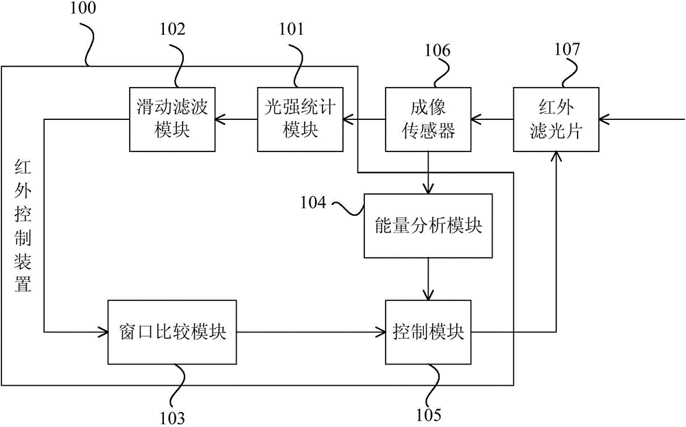
[0089] figure 1 It is a schematic structural diagram of the infrared control device provided by Embodiment 1 of the present invention. The infrared control device of this embodiment is suitable for cameras with infrared lamps and infrared filters. Wherein, the camera may be, for example, an IP camera (IP Camera, IPC for short) or a video surveillance device. like figure 1 As shown, the infrared control device 100 of this embodiment includes: a light intensity statistics module 101 , a sliding filter module 102 , a window comparison module 103 , an energy analysis module 104 and a control module 105 . The light intensity statistics module 101, the sliding filter module 102, the window comparison module 103 and the control module 105 are connected in sequence.

[0090] The light intensity statistics module 101 is also connected to an imaging sensor (sensor) 106 , and is used to calculate the average light receiving intensity of the imaging sensor 106 according to the imaging ...

Embodiment 2

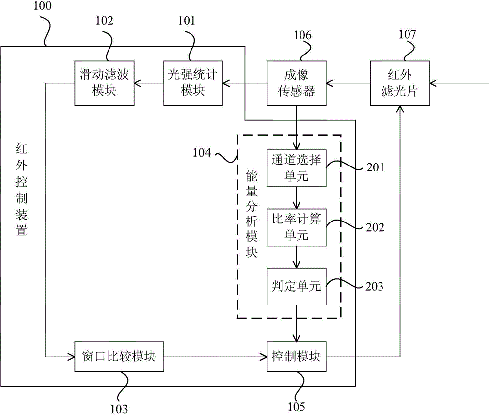
[0106] This embodiment also provides an infrared control device. figure 2 It is a schematic structural diagram of the infrared control device provided by Embodiment 2 of the present invention. On the basis of the above scheme, if figure 2 As shown, the energy analysis module 104 includes: a channel selection unit 201 , a ratio calculation unit 202 and a determination unit 203 . The imaging sensor 106 includes: at least one group of photosensitive elements; each group of photosensitive elements includes: an R photosensitive element, a Gr photosensitive element, a Gb photosensitive element, and a B photosensitive element.

[0107] The group of photosensitive elements corresponds to one pixel point, and one pixel point includes four photosensitive points. The four photosensitive points are points corresponding to the R photosensitive element, the Gr photosensitive element, the Gb photosensitive element and the B photosensitive element.

[0108] The channel selection unit 201...

Embodiment 3

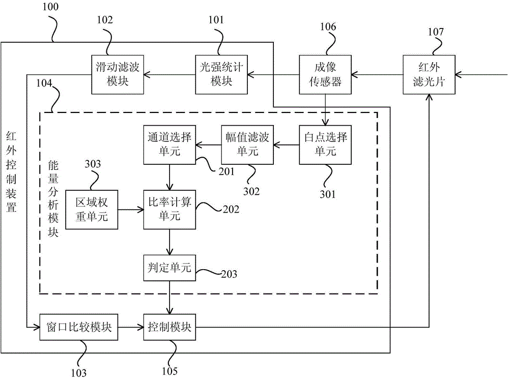
[0118] This embodiment also provides an infrared control device. image 3 It is a schematic structural diagram of the infrared control device provided by Embodiment 3 of the present invention. like image 3 As shown, the energy analysis module 104 further includes a white point selection unit 301 .

[0119] The white point selection unit 301 is connected with the imaging sensor 106 and the channel selection unit 201 for selecting white point data in the imaging data, and sending the selected white point data to the channel selection unit 201 .

[0120] The channel selection unit 201 is further configured to respectively determine the light intensity of each element in the at least one group of photosensitive elements according to the white point data.

[0121]Specifically, the white point data may be data that conforms to white balance in the imaging data. It should be noted that the white point data in this embodiment is not absolute white point data, that is, the correspo...


PUM


Abstract

Provided are an infrared control device and method, and a camera. The infrared control device of the present invention comprises: a light intensity counting module, a sliding filtering module, a window comparison module, an energy analysis module and a control module, wherein the light intensity counting module counts an average sensed light intensity according to imaging data; the sliding filtering module filters the average sensed light intensity; the window comparison module compares the average sensed light intensity to an open threshold value, and if the average sensed light intensity is greater than the open threshold, a first control signal is output; the energy analysis module conducts an energy analysis according to the imaging data so as to judge the state of an infrared lamp, if the infrared lamp is turned on, a second control signal is sent, and if the infrared lamp is turned off, a third control signal is sent; and the control module controls the infrared filter to be turned off according to the first control signal and the second control signal, and controls the infrared filter to be turned on according to the first control signal and the third control signal. The embodiments of the present invention can improve the imaging stability of a camera.

Description

technical field [0001] Embodiments of the present invention relate to information processing technologies, and in particular to an infrared control device, method and camera. Background technique [0002] The visible light that can be seen by the human eye is arranged according to the wavelength from long to short, in order of red, orange, yellow, green, cyan, blue, and purple. Among them, the wavelength of red light ranges from 0.62 to 0.76 μm; light with a longer wavelength than red light is called infrared, and human eyes cannot see infrared. Since the photosensitive unit of the camera senses and captures all incident light, including visible light, infrared rays, etc. In order to avoid the influence of infrared rays on the image color after imaging, an infrared filter is installed between the lens of the camera and the photosensitive unit to filter out infrared rays, so that the photosensitive unit can only sense visible light. [0003] However, in order to improve the...

Claims


Application Information

Patent Timeline
IPC IPC(8): H04N5/232H04N5/225H04N5/33
CPCH04N23/56H04N23/55H04N23/11
Inventor 李健璋许锡雷王斌
Owner HANGZHOU HUAWEI ENTERPRISE COMM TECH
Why Eureka
Try Eureka