Wet dust collector

A technology of wet dust collector and mist eliminator, which is applied in the field of machinery, can solve the problems of limited space at the reloading point, small amount of flue gas to be dusted, and large dust and water vapor content, and achieves good dust removal stability, compact structure, Ease of inspection and maintenance

Inactive Publication Date: 2015-10-21
郝胜元
View PDF6 Cites 0 Cited by
  • Summary
  • Abstract
  • Description
  • Claims
  • Application Information

AI Technical Summary

Problems solved by technology

[0002] At present, in the process of belt conveying and reloading after mineral drying, especially coal drying, the dust is flying and the water vapor content is extremely large, which seriously affects the surrounding working environment. In order to reduce the impact of dust on the environment, a variety of dust removal and dust suppression measures are taken. However, due to the limited space of the transfer point, the small amount of flue gas to be dedusted, and the high moisture content of the flue gas, there are limitations. A large amount of water vapor, the filter medium is easily blocked due to water mist condensation, so it is urgent to provide solutions for this type of problem in industrial applications

Method used


Image

  • Wet dust collector
  • Wet dust collector

Examples


Embodiment 1

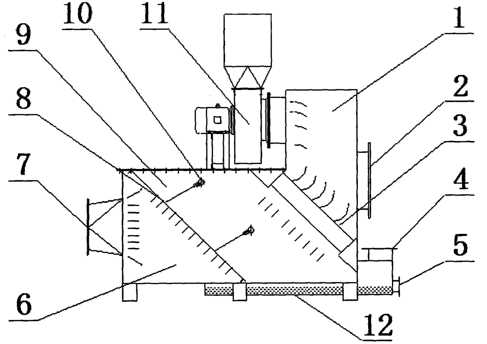
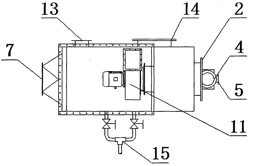
[0020] Such as figure 1 and figure 2 As shown, a wet dust collector includes a housing, a fan 11, a water supply pipe 15, a dehydration demister 3, and a drainage tank 12. It is characterized in that: the housing is provided with a cavity, and the housing There are inlets and outlets connected internally and externally. The outer surface of the housing is provided with a number of inspection holes and manholes. The housing is equipped with a titanium silk curtain mesh plate 8, a spray pipe 10, dehydration and defogging device 3, the titanium wire curtain mesh plate 8 is provided with evenly distributed through holes; the titanium wire curtain mesh plate 8 and the dehydration demister 3 are sequentially arranged in the housing and sequentially divide the inner shell The cavity is three cavities, and the three cavities from left to right are the air inlet chamber 6, the dust removal chamber 9, and the exhaust chamber 1; one side of the air inlet chamber 6 is provided with an a...

Embodiment 2

[0023] Such as figure 1 and figure 2 As shown, a wet dust collector includes a housing, a fan 11, a water supply pipe 15, a dehydration demister 3, and a drainage tank 12. It is characterized in that: the housing is provided with a cavity, and the housing There are inlets and outlets connected internally and externally. The outer surface of the housing is provided with a number of inspection holes and manholes. The housing is equipped with a titanium silk curtain mesh plate 8, a spray pipe 10, dehydration and defogging device 3, the titanium wire curtain mesh plate 8 is provided with evenly distributed through holes; the titanium wire curtain mesh plate 8 and the dehydration demister 3 are sequentially arranged in the housing and sequentially divide the inner shell The cavity is three cavities, and the three cavities from left to right are the air inlet chamber 6, the dust removal chamber 9, and the exhaust chamber 1; one side of the air inlet chamber 6 is provided with an a...


PUM


Abstract

The invention relates to a wet dust collector which comprises a casing, a motor, a water supply pipe, a demister and drainage channels, wherein a cavity is formed in the casing; a plurality of access holes and manholes are formed in the outer surface of the casing; a titanium wire screen pore plate, a plurality of spraying pipelines and the dehydration demister are arranged in the casing; uniformly distributed through holes are formed in the titanium wire screen pore plate; the titanium wire screen pore plate and the dehydration demister are sequentially arranged in the casing, and divide the casing into an air inlet chamber, a dust collection chamber and an exhaust chamber; an air inlet is formed in one side of the air inlet chamber; the other side of the air inlet chamber is communicated with the dust collection chamber through the titanium wire screen pore plate; the drainage channels are communicated with the lower parts of the air inlet chamber and the dust collection chamber; the spraying pipelines are arranged in the dust collection chamber; the dehydration demister is arranged between the dust collection chamber and the exhaust chamber; the fan is arranged at the outlet of the exhaust chamber. The wet dust collector has the advantages of being small in size, compact in structure, high in dust collection stability, and long in service life.

Description

technical field [0001] The invention belongs to the technical field of machinery, and in particular relates to a wet dust collector. Background technique [0002] At present, in the process of belt conveying and reloading after mineral drying, especially coal drying, the dust is flying and the water vapor content is extremely large, which seriously affects the surrounding working environment. In order to reduce the impact of dust on the environment, a variety of dust removal and dust suppression measures are taken. However, due to the limited space of the transfer point, the small amount of flue gas to be dedusted, and the high moisture content of the flue gas, there are limitations. With a large amount of water vapor, the filter medium is easily blocked due to water mist condensation, so it is urgent to provide solutions for this type of problem in industrial applications. Contents of the invention [0003] The purpose of the present invention is to overcome the deficien...

Claims


Application Information

Patent Timeline
Patent Type & Authority Applications(China)
IPC IPC(8): B01D50/00
Inventor 郝胜元
Owner 郝胜元
Why Eureka
Try Eureka