Desulfurization tower flue gas nozzle and desulfurization apparatus
A desulfurization device, desulfurization tower technology, applied in the direction of dispersed particle separation, chemical instruments and methods, separation methods, etc., can solve the problems of full contact of desulfurization liquid, low desulfurization efficiency, short reaction time, etc., to prolong contact time and reaction time , Improve desulfurization efficiency and reduce volume
- Summary
- Abstract
- Description
- Claims
- Application Information
AI Technical Summary
Problems solved by technology
Method used
Image

Examples
Embodiment
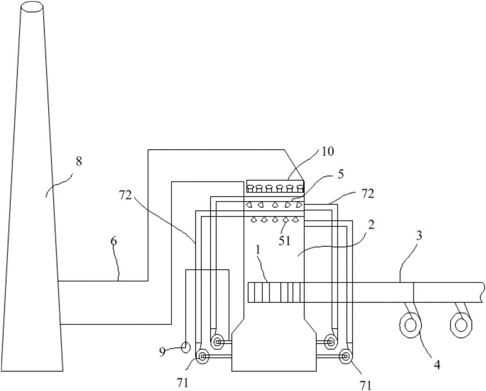
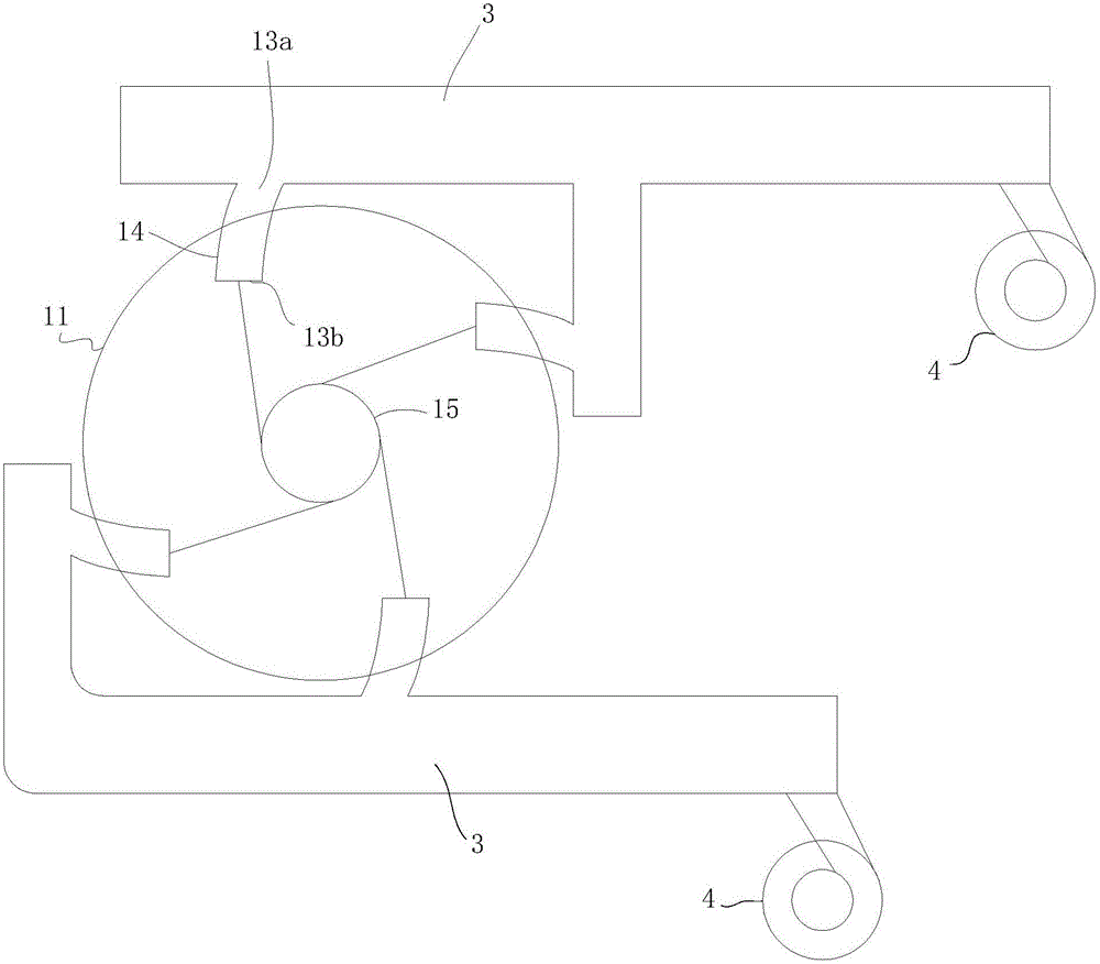
[0056] see figure 1 , figure 2 , the embodiment of the present invention provides a desulfurization flue gas nozzle 1, which includes a cylindrical nozzle body 11; a group of nozzle bodies (referred to as the nozzle body 11) are provided around the nozzle body 11 for feeding into it (referred to as the nozzle body 11). The smoke in the nozzle hole 13) forms the nozzle hole 13 of swirling flow; the end of the nozzle hole 13 away from the center of the nozzle body 11 is the smoke inlet 13a; the end of the nozzle hole 13 near the center of the nozzle body 11 is the smoke outlet 13b.
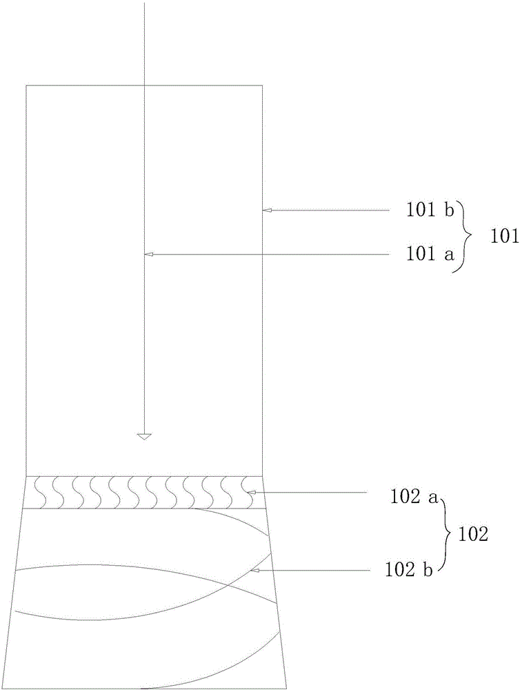
[0057] The flue gas enters the nozzle hole 13 through the flue gas inlet 13a, is sprayed out through the flue gas outlet 13b, forms a swirling flow inside the nozzle body 11, and enters the absorption tower upward through the inner hole 12 of the nozzle body 11, and the desulfurization liquid in the absorption tower Full contact and desulfurization reaction. The nozzle body 11 in this embodiment ...
Embodiment 1
[0059] see figure 1 A group of injection pipes 14 are arranged on the nozzle body 11 , and the inner holes of the injection pipes 14 form injection holes 13 . When the tube wall of the nozzle body 11 is thinner, a jet tube 14 can be set on the tube wall of the nozzle body 11, and the jet tube 14 can be arranged outside the nozzle body 11, can also be arranged inside the nozzle body 11, and can also be inserted in the nozzle body 11. On the nozzle body 11, but the spray pipe 14 and the nozzle body 11 need to be sealed and connected, and the relative positional relationship needs to be fixed, generally by welding or detachable connection. The injection pipes 14 can be arranged vertically or horizontally, and a valve can be set on each injection pipe 14 to adjust the amount of flue gas.
Embodiment 2
[0061] see figure 2 , the nozzle hole 13 is formed in the peripheral wall of the nozzle body 11 . When the pipe wall of the nozzle body 11 is relatively thick, spray holes 13 can be provided in the pipe wall of the nozzle body 11 .
[0062] On the basis of the above embodiments, the nozzle body 11 is arranged horizontally in the absorption tower; the nozzle hole 13 is arranged obliquely downward from the flue gas inlet 13a to the flue gas outlet 13b. It can prevent the reflux in the nozzle hole from the slurry inside the absorption tower.
[0063] A reverse flushing pipe for preventing the nozzle hole 13 from being clogged may also be provided in the nozzle hole 13 . Water flow is passed into the flushing pipe to prevent the backflowing slurry from solidifying and blocking the nozzle hole 13.
[0064] The concrete cross-sectional shape of injection pipe 14 can be circular, square or ellipse etc., and injection pipe 14 can be straight pipe or arc bend pipe is arranged, and ...
PUM
 Abstract
Description
Claims
Application Information
 - R&D
- Intellectual Property
- Life Sciences
- Materials
- Tech Scout
- Unparalleled Data Quality
- Higher Quality Content
- 60% Fewer Hallucinations
Browse by: Latest US Patents, China's latest patents, Technical Efficacy Thesaurus, Application Domain, Technology Topic, Popular Technical Reports.
© 2025 PatSnap. All rights reserved.Legal|Privacy policy|Modern Slavery Act Transparency Statement|Sitemap|About US| Contact US: help@patsnap.com