
Planet flour mill

A grinding machine and planetary technology, which is applied in the field of planetary grinding machines, can solve the problems of abrasive wear, large floor space, and high noise, and achieve the effects of improved service life, small floor space, and high discharge efficiency

Inactive Publication Date: 2015-10-21
陈韧坚
View PDF8 Cites 2 Cited by
  • Summary
  • Abstract
  • Description
  • Claims
  • Application Information

AI Technical Summary

Problems solved by technology

[0002] At present, there are many kinds of grinding machines used for grinding in the society, such as tubular ball mill, Raymond mill, vertical mill, rod mill, horizontal roller mill, etc. These grinding machines occupy a large area and have many consumable parts. , high noise, high energy consumption
CN201210422252 discloses a planetary pulverizer. Most of the crushing rollers of this pulverizer are cylindrical structures, which are not convenient for discharging; at the same time, there is only one group of crushing rollers distributed along the circumference in the cylinder of the pulverizer, and the discharging The tube is located on one side of the cylinder, and can only be discharged from one side, and the grinding efficiency and discharge efficiency are low
[0003] At the same time, the gap between the crushing roller and the wear-resistant lining is difficult to control. When the pulverizer is started, the crushing roller is in contact with the wear-resistant lining. Necessary abrasive wear
[0004] In addition, the existing pulverizer is difficult to control the thickness of the material layer, and it is difficult to realize the rolling of thin material layers

Method used


Image

  • Planet flour mill
  • Planet flour mill

Examples


Embodiment Construction

[0024] The present invention will be further described in detail below in conjunction with the accompanying drawings and specific embodiments.

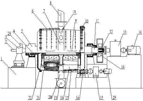
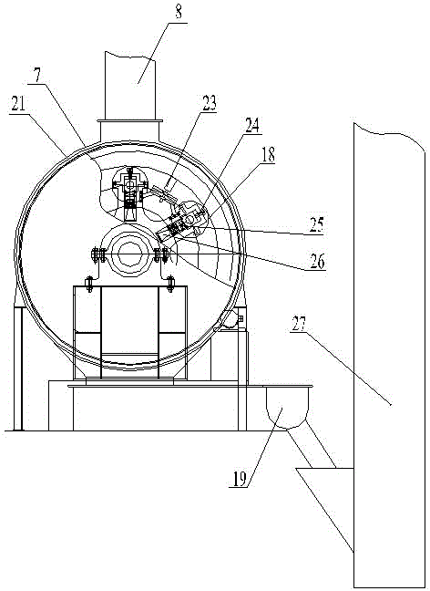
[0025] refer to figure 1 , the present embodiment includes a horizontally arranged main shaft 11, the interior of the main shaft 11 is hollow, a planetary support 22 is provided in the middle of the main shaft 11, the planetary support 22 is fixedly connected with the main shaft 11, and a group of crushing rollers 18 are arranged on both sides of the planetary support 22. The material rollers 18 are circumferentially distributed in the vertical plane, and the material rollers 18 are in a circular platform structure; The surface is a circular arc surface with a transverse slope that fits closely with the circular table surface of the scrap roller 18; the inner surface of the cylinder 21 is provided with a wear-resistant lining plate 17, and the two ends of the cylinder 21 are provided with a cylinder hollow shaft 4, and the cylinder bo...


PUM


Abstract

A planet flour mill comprises a spindle. The spindle is hollow. A planet support is arranged in the middle of the spindle. The two sides of the planet support are each provided with a set of crushing rollers which are circumferentially distributed in a vertical face. The crushing rollers are of a truncated-cone structure. A barrel is arranged outside the crushing rollers. The inner surface of the barrel is an arc-shaped face which is tightly attached to the truncated-cone faces of the crushing rollers and has the cross slope. An anti-abrasive liner plate is arranged on the inner surface of the barrel. Hollow barrel shafts are arranged at the two ends of the barrel. The barrel is movably connected with the spindle through the hollow barrel shafts. A discharging port is formed in the middle of the outer wall of the barrel in the circumferential direction. A dust cover is arranged outside the barrel. A discharging pipe is arranged at the bottom of the dust cover. A spraying port is formed in the middle of the spindle. A feeder is arranged at the feeding end of the spindle and provided with a feeding pipe and a feeding air pipe. A spindle power system and a hollow barrel shaft power system are further arranged. The spindle power system is connected with the spindle. The hollow barrel shaft power system is connected with the hollow barrel shafts. The planet flour mill is high in flour milling efficiency and discharging efficiency and materials are convenient to discharge.

Description

technical field [0001] The invention relates to a planetary pulverizer. Background technique [0002] At present, there are many kinds of grinding machines used for grinding in the society, such as tubular ball mill, Raymond mill, vertical mill, rod mill, horizontal roller mill, etc. These grinding machines occupy a large area and have many consumable parts. , high noise and high energy consumption. CN201210422252 discloses a planetary pulverizer. Most of the crushing rollers of this pulverizer are cylindrical structures, which are not convenient for discharging; at the same time, there is only one group of crushing rollers distributed along the circumference in the cylinder of the pulverizer, and the discharging The tube is located on one side of the cylinder, and can only be discharged from one side, and the grinding efficiency and discharge efficiency are low. [0003] At the same time, the gap between the crushing roller and the wear-resistant lining is difficult to co...

Claims


Application Information

Patent Timeline
IPC IPC(8): B02C15/06
Inventor 陈韧坚
Owner 陈韧坚
Learn More