Spacers, Ribbed Floors Using Spacers and Construction Formwork Systems

A technology of dense-ribbed floor and positioning parts, applied in the field of construction, can solve the problems of low reliability, poor safety, low efficiency, etc., and achieve the effect of widening the application scope, low cost, and convenient disassembly and assembly.

Active Publication Date: 2017-11-14
张玉华
View PDF3 Cites 0 Cited by
  • Summary
  • Abstract
  • Description
  • Claims
  • Application Information

AI Technical Summary

Problems solved by technology

[0002] The position of the bottom reinforcement or the thickness of the protective layer in concrete beams, slabs and other components are usually guaranteed by prefabricated pads and supports. For example, the authorized announcement number is CN202672497U, the announcement date: 2013.01.16, and the invention name is "Concrete Protective Layer Block" , The authorized announcement number is CN202299144U, the announcement date: 2012.07.04, the invention name is "a reinforced concrete protective layer pad", the authorized announcement number is CN204001442U, the announcement date: 2014.12.10, the invention name is "a steel bar support 》And other technical solutions, place blocks or supports on the formwork to support the steel bars, this type of program has defects, such as not being able to limit the floating of the steel bars, no limit to the horizontal movement, and the reliability is not very high
[0003] In densely ribbed slabs, the size of the rib beam and the position of the lower reinforced reinforcement are more important, and there is still a lack of a simpler method
In addition, for densely ribbed floors with filling blocks, permanent formwork and other components, the formwork system is often fully supported, and the steel formwork or plywood is fully paved. Formwork support and installation of formwork or filling blocks require a lot of on-site aerial work, which is inefficient. poor security

Method used


Image

  • Spacers, Ribbed Floors Using Spacers and Construction Formwork Systems
  • Spacers, Ribbed Floors Using Spacers and Construction Formwork Systems
  • Spacers, Ribbed Floors Using Spacers and Construction Formwork Systems

Examples


Embodiment 1

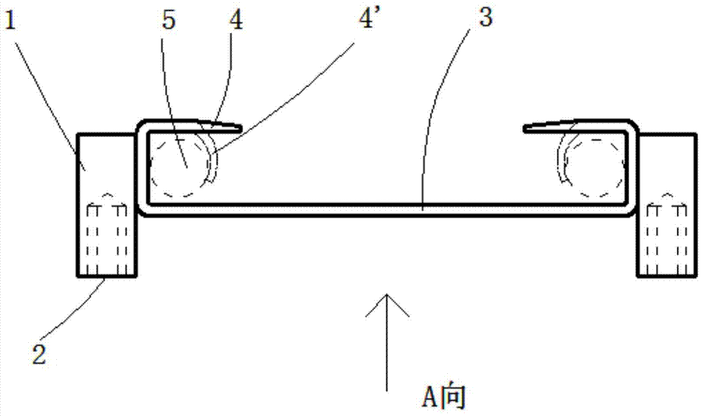
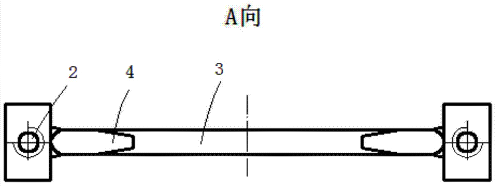
[0054] Such as figure 1 , figure 2As shown, the two ends of the cross support 3 are respectively provided with retaining legs 1, and the retaining legs 1 are used as a limiting part, and the outer surface resists the side wall of the permanent template or the filling block to limit the position. The bottom of the retaining leg 1 is provided with a screw hole a2 for For its own fixing, the buckle 4 is a fixed steel bar component, the longitudinal bar 5 at the bottom of the rib beam is bent from the buckle 4 to the position where the buckle bends 4' for fixing, and the positioning part is a steel part.

Embodiment 2

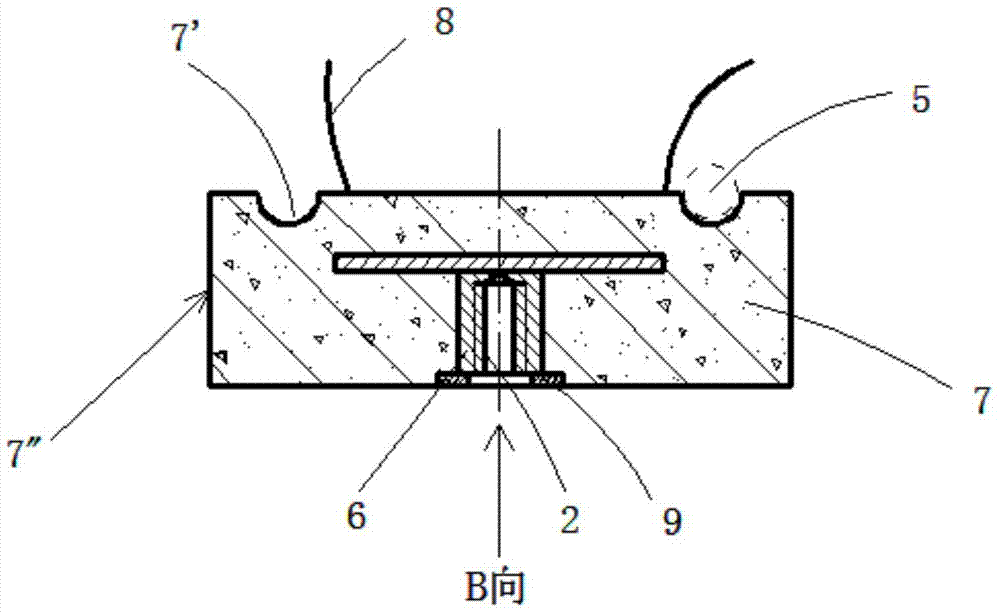
[0056] Such as image 3 and Figure 4 As shown, the base 6 is embedded in the concrete pad 7, the bottom surface of the base 6 is provided with a screw hole a2 through the bottom, a gasket 9 is also provided under the screw hole a2, and a groove 7' and a binding wire 8 are provided on the concrete pad 7. , used to fix the longitudinal reinforcement 5 at the bottom of the rib beam, and the two ends of the concrete pad 7, as a retaining edge 7", blocking the spacing or position of the permanent formwork or filling block.

Embodiment 3

[0058] Such as Figure 5 , Figure 6 As shown, the two ends of the cross support 3 are provided with retaining legs 1', the lower part is provided with a leg 11, the right leg 11 is provided with a screw hole b12, the left leg is provided with a light hole 12', and a matching nut b13 is placed on it. The leg structures on both sides can be substituted for each other. The horizontal support 3 is provided with a bolt hole 10 to fix the binding wire 8, and the binding wire 8 fixes the longitudinal rib 5 at the bottom of the rib beam.


PUM


Abstract

The invention discloses a positioning piece, which includes a fixed steel bar part, a limit part and a self-positioning structure, the fixed steel bar part is a buckle, a collar, a tie hole or a wire, and the limit part is a leg or a side bar or a bar or a bar The self-fixing structure of the block is a down-through screw hole or a clamping hole provided on the bottom surface of the retaining leg or the foot or the base. The positioning piece makes the size of the rib beam and the position of the steel bar accurate and reliable; the invention discloses a densely ribbed floor, including a rib beam, an upper panel, and a permanent formwork or a filling block, and the side wall of the permanent formwork or filling block is a side formwork or a rib beam / and the superimposed surface, the lower part of the rib beam also contains a positioning piece. The dense rib floor is convenient for construction and low in cost. The invention discloses a construction formwork system, which includes a joist and a permanent formwork or a filling block, and also includes a positioning piece, a plurality of positioning pieces are arranged at intervals, fixed on the top surface of the joist by a fastener that can be detached from the bottom, and the permanent formwork or filling block The interval forms the rib beam cavity. The construction formwork system is simple and reliable, with less aerial work.

Description

technical field [0001] The invention belongs to the technical field of construction and relates to a positioning piece. The invention also relates to a ribbed floor using the positioning piece. The invention also relates to a construction formwork system for a densely ribbed floor using the positioning piece. Background technique [0002] The position of the bottom reinforcement or the thickness of the protective layer in concrete beams, slabs and other components are usually guaranteed by prefabricated pads and supports. For example, the authorized announcement number is CN202672497U, the announcement date: 2013.01.16, and the invention name is "Concrete Protective Layer Block" , The authorized announcement number is CN202299144U, the announcement date: 2012.07.04, the invention name is "a reinforced concrete protective layer pad", the authorized announcement number is CN204001442U, the announcement date: 2014.12.10, the invention name is "a steel bar support 》And other tec...

Claims


Application Information

Patent Timeline
Patent Type & Authority Patents(China)
IPC IPC(8): E04C5/16E04B5/18E04G11/48
Inventor 张玉华
Owner 张玉华
Why Eureka
Try Eureka