A mid-set VVT engine oil control valve

An oil control valve, center-mounted technology, applied to non-mechanically actuated valves, valve devices, mechanical equipment, etc., can solve the problems of increasing engine manufacturing costs, controlling the length of the oil circuit, and improving the speed of response and control Stability, simplification of the engine cylinder head structure, and the effect of reducing manufacturing costs

Active Publication Date: 2015-10-21
MIANYANG FULIN PRECISION MACHINING
View PDF4 Cites 16 Cited by
  • Summary
  • Abstract
  • Description
  • Claims
  • Application Information

AI Technical Summary

Problems solved by technology

[0003] In the existing engine variable cam timing system, the phaser is installed on the camshaft through a separate connection with screws, and the oil control valve is a separate assembly independent of the phaser. Since the oil control valve is installed on the engine cylinder head In fact, it controls the phaser through many sets of oil passages, which leads to a complex structure of the engine cylinder head and increases the manufacturing cost of the engine. Therefore, the engine variable cam timing system is relatively poor in response speed and control stability, which is not conducive to the improvement of engine fuel combustion efficiency, so that the purpose of engine fuel saving cannot be well achieved

Method used


Image

  • A mid-set VVT engine oil control valve
  • A mid-set VVT engine oil control valve
  • A mid-set VVT engine oil control valve

Examples


Embodiment Construction

[0022] In order to make the object, technical solution and advantages of the present invention clearer, the present invention will be described in detail below in conjunction with the accompanying drawings and specific embodiments. It should be understood that the specific embodiments described here are only used to explain the present invention, not to limit the present invention.

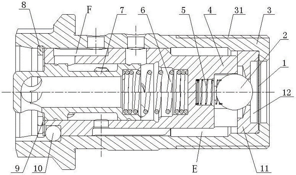
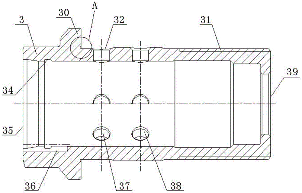
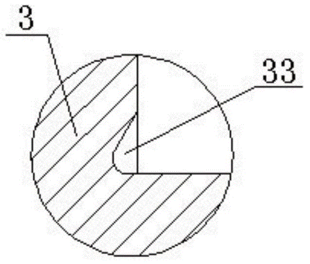
[0023] Such as figure 1 A mid-mounted VVT oil control valve shown includes a valve body 3, a check valve and a valve core 7, and the specific structure of the valve body 3 is as follows: figure 2 , image 3 As shown, the inner cavity of the valve body 3 is completely connected in a stepped shape, the opening at the left end is the oil outlet 35, and the opening at the right end is the oil inlet 39. A threaded connection 31 is arranged on the outer circle of the oil inlet end of the valve body 3. A shoulder 30 is set on the outer circle of the oil outlet end of the body 3, and a relief groove 33...


PUM


Abstract

The invention provides a mid-set VVT engine oil control valve comprising a one-way valve, a valve body and a valve element. The oil inlet end of the valve body is provided with a thread connecting part; the one-way valve is installed in an inner cavity of the valve body; the mid-set VVT engine oil control valve also comprises a valve sleeve, a valve seat, a rolling ball body and a spring; one end of the valve sleeve is provided with a rolling ball body installing hole and the other end is provided with a valve element installing hole, a first oil hole, a second oil hole and a third oil hole; the valve seat is provided with a through hole communicated with an oil inlet of the valve body; the rolling ball body is installed between the rolling ball body installing hole and the valve seat through hole; an oil inlet channel is formed between the valve seat through hole and the third oil hole; the spring is arranged between the valve sleeve and the rolling wall body; a resetting spring is arranged between the valve element and the valve sleeve. With the mid-set VVT engine oil control valve, the response speed and the control stability of an engine variable cam timing system are greatly improved; an engine cylinder cover installing hole and corresponding oil channels are not needed, so that the engine cylinder cover structure is simplified and the manufacture cost of engines is reduced.

Description

technical field [0001] The invention relates to an engine oil control valve, in particular to a mid-mounted VVT engine oil control valve used for phase adjustment of a variable cam timing system of an engine. Background technique [0002] The principle of VVT (Variable Valve Timing, engine variable valve timing technology) is to adjust the amount of intake (exhaust) and the opening and closing time and angle of the valve according to the operating conditions of the engine, so that the amount of air entering the engine can be optimized, so as to Improve the fuel combustion efficiency of the engine to achieve the purpose of saving fuel. At present, there are two types of oil control valves used in engine variable cam timing systems: side-mounted oil control valves and mid-mounted oil control valves. Technical upgrades on the mounted oil control valve. [0003] In the existing engine variable cam timing system, the phaser is installed on the camshaft through a separate connec...

Claims


Application Information

Patent Timeline
Patent Type & Authority Applications(China)
IPC IPC(8): F01L1/344F01L9/02
Inventor 谭建伟向明朗赵敬刚张金伟
Owner MIANYANG FULIN PRECISION MACHINING
Why Eureka
Try Eureka