Check patentability & draft patents in minutes with Patsnap Eureka AI!

Magnetorheological damper with stepless and adjustable damping force

A magnetorheological shock absorber and damping force technology, applied in the direction of shock absorbers, shock absorbers, springs/shock absorbers, etc., can solve the problems of incapable of damping, fixed and complex structure, etc. Achieve the effect of continuously variable damping force, prolong service life and improve comfort

Inactive Publication Date: 2015-10-21
WUHU XINGZHONG IMPORT & EXPORT
View PDF7 Cites 1 Cited by
  • Summary
  • Abstract
  • Description
  • Claims
  • Application Information

AI Technical Summary

Problems solved by technology

[0002] At present, the traditional passive suspension shock absorber is widely used in domestic automobiles. The damping coefficient and spring stiffness of this shock absorber are fixed and cannot play a good damping effect; while the active suspension can theoretically obtain An ideal vibration isolation system achieves the ideal suspension control goal, but it consumes a lot of energy, costs high, and has a complex structure; the cylindrical magneto-rheological shock absorber in the semi-active suspension effectively solves the problem of passive suspension. The contradiction between comfort and stability, and the control effect is also close to the performance of active suspension, and the structure is simple, the price is relatively cheap, and it does not need to provide additional energy and can generate a variety of damping forces. Better balance of riding comfort and handling stability

Method used


Image

  • Magnetorheological damper with stepless and adjustable damping force
  • Magnetorheological damper with stepless and adjustable damping force
  • Magnetorheological damper with stepless and adjustable damping force

Examples


Embodiment

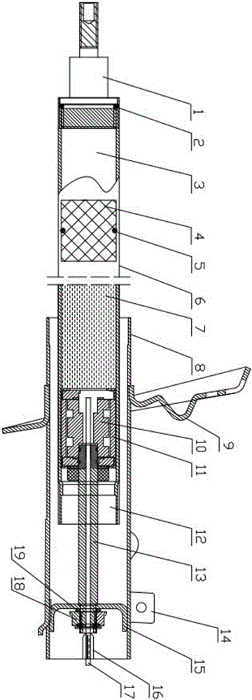
[0033] Such as Figures 1 to 4 As shown, a magnetorheological shock absorber with steplessly adjustable damping force, the magnetorheological shock absorber includes an outer cylinder assembly, an inner cylinder assembly and a piston rod assembly, and the outer cylinder assembly is set On the periphery of the inner cylinder assembly, the piston rod assembly is arranged inside the inner cylinder assembly and the outer cylinder assembly.

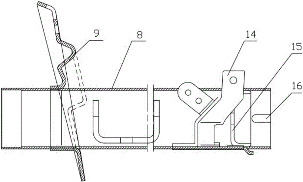
[0034] The outer cylinder assembly mainly includes an outer cylinder 8, a spring tray 9 arranged on the outside of the outer cylinder 8 for supporting the limit damping spring, an oil pipe fixing bracket 14 arranged on the outside of the outer cylinder 8 for fixing the oil pipe, and a set The piston rod fixing bracket 15 used for fixing the piston rod 13 is used for fixing the piston rod 13 at the inner rear end of the outer cylinder 8 .

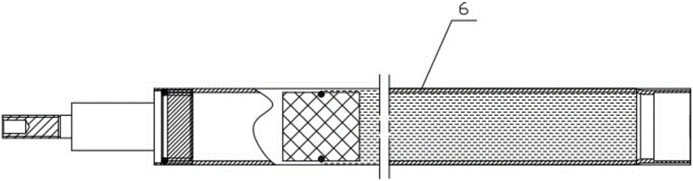
[0035] The inner cylinder assembly mainly includes an inner cylinder 6; a floating valve body 4 is arran...


PUM


Abstract

The invention provides a magnetorheological damper with stepless and adjustable damping force. The magnetorheological damper comprises an outer cylinder assembly, an inner cylinder assembly and a piston rod assembly, wherein the outer cylinder assembly is arranged on the periphery of the inner cylinder assembly, and the piston rod assembly is arranged inside the inner cylinder assembly and the outer cylinder assembly. The outer cylinder assembly mainly comprises an outer cylinder, a spring pallet, an oil pipe fixing support and a piston rod fixing support. The inner cylinder assembly mainly comprises an inner cylinder. A floating valve body is arranged inside the inner cylinder. The front end of the floating valve body is filled with high pressure gas, and the rear end of the floating valve body is filled with magnetorheological liquid. A guide oil seal is arranged at the rear end of the inner cylinder. The piston rod assembly mainly comprises a piston rod and a piston assembly. The piston assembly comprises a piston body and a coil protecting shell, wherein a coil is wound around the piston body, the coil protecting shell sleeves the piston body, and the coil is connected with a control system arranged outside the magnetorheological damper through a signal wire. By the adoption of the magnetorheological damper, the viscosity of damping liquid of the magnetorheological damper is adjustable, and stepless changing of damping can be achieved.

Description

technical field [0001] The invention relates to a shock absorber, in particular to a magneto-rheological shock absorber with steplessly adjustable damping force. Background technique [0002] At present, traditional passive suspension shock absorbers are widely used in domestic automobiles. The damping coefficient and spring stiffness of this shock absorber are fixed and cannot play a good damping effect; while active suspensions can theoretically obtain An ideal vibration isolation system achieves the ideal suspension control goal, but it consumes a lot of energy, costs high, and has a complex structure; the cylindrical magneto-rheological shock absorber in the semi-active suspension effectively solves the problem of passive suspension. The contradiction between comfort and stability, while the control effect is also close to the performance of active suspension, and the structure is simple, the price is relatively cheap, and it does not need to provide additional energy an...

Claims


Application Information

Patent Timeline
IPC IPC(8): F16F9/53
CPCF16F9/535
Inventor 杨贵祥
Owner WUHU XINGZHONG IMPORT & EXPORT
Features
  • R&D
  • Intellectual Property
  • Life Sciences
  • Materials
  • Tech Scout
  • Unparalleled Data Quality
  • Higher Quality Content
  • 60% Fewer Hallucinations
Learn More