TR element locating and defect detecting method based on vision

A defect detection and component technology, applied in the direction of optical testing flaws/defects, etc., can solve problems such as poor real-time performance, human error, and low accuracy

Active Publication Date: 2015-10-21
宁波智能装备研究院有限公司
View PDF5 Cites 23 Cited by
  • Summary
  • Abstract
  • Description
  • Claims
  • Application Information

AI Technical Summary

Problems solved by technology

[0006] The purpose of the present invention is to solve the problems of artificial errors, low precision, poor real-time performance and sensitivity ...

Method used


Image

  • TR element locating and defect detecting method based on vision
  • TR element locating and defect detecting method based on vision
  • TR element locating and defect detecting method based on vision

Examples


specific Embodiment approach 1

[0075] Specific implementation mode 1: The vision-based TR component positioning and defect detection method of this embodiment is specifically prepared according to the following steps:

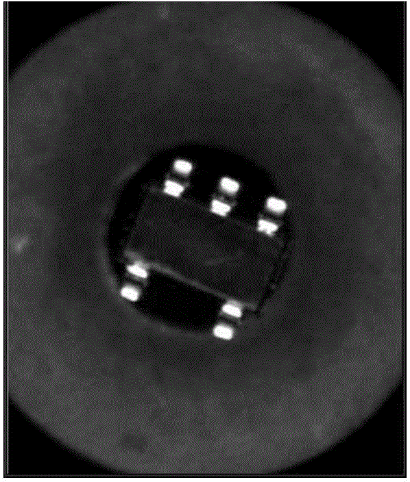
[0076] Step 1. Check the selected area image ( figure 1 ) Brightness; if the image appears too bright or too dark, stop checking and return the corresponding error code; if the ratio of the number of bright spots to the total number of dots is in the interval [0.01, 0.90], go to step 2; where the pixel value in the selected area image 255 pixels are regarded as bright spots, and the number of all pixels in the selected area image is recorded as the total number of points; when the ratio of the number of bright spots to the total number of points is less than 0.01, the area image is considered too dark, and when the ratio of the number of bright spots to the total number of points is greater than 0.90, it is considered The area image is too bright;

[0077] Step 2: Binarize the image with the rat...

specific Embodiment approach 2

[0125] Specific embodiment two: this embodiment is different from specific embodiment one in that in step two, the ratio of the number of bright spots to the total number of points in the selected area image is binarized to obtain a binarized image There are two specific implementation methods:

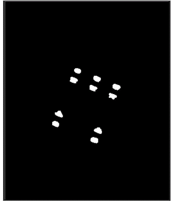
[0126] The first is to manually input the fixed threshold binarization method, that is, set the pixel value greater than or equal to the input threshold to 255, and set the pixel value less than the input threshold to 0, and get the manual input fixed threshold binarization method. Binary image such as figure 2 ;

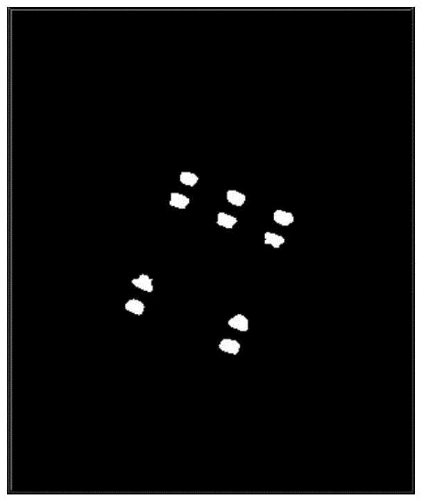
[0127] The second method is the method with the largest variance between classes (Otsu method or Otsu method) to obtain a binary image obtained by the method with the largest variance between classes, such as image 3 ;

[0128] Manually enter the binarized image obtained by the fixed threshold binarization method and the binarized image obtained by the method with the largest v...

specific Embodiment approach 3

[0129] Specific embodiment three: this embodiment is different from specific embodiment one or two in that in step seven, the effective boundary point set obtained in step four is divided into the upper effective boundary point set of the TR element and the lower effective boundary point set of the TR element according to α. The classification methods for the two groups are:

[0130] (1) If the rough rotation angle α of the component obtained in step 5 is outside plus or minus 30 degrees, it will stop, and an error code indicating that the rotation angle is too large will be output. If α is within the range of plus or minus 30 degrees, proceed to step (2) ;

[0131] (2) The unit vector pointing to the effective boundary point set of the lower part of the TR element is obtained by the rough rotation angle α of the TR element a → = ( - s i n α , c o s α ) ;

[0132] (3) Take the rough center of the TR element (x 0 ,y 0 ) Is the starting point, p...


PUM


Abstract

The invention discloses a TR element locating and defect detecting method based on vision and relates to a TR element vision locating and defect detecting method based on the vision. The TR element locating and defect detecting method based on the vision solves the problems that in the prior art personal errors exist, the precision is low, the real-time performance is poor, and the calculation result is sensitive to illumination. The TR element locating and defect detecting method based on the vision is achieved through the steps that an area image is binarized, an outer boundary point set is extracted, an effective boundary point set is searched, a minimum enclosing rectangle is searched, the effective boundary point set is classified, affine transformation is conducted on the binary image, the type of the TR element is checked, the effective boundary point set is classified again and numbered, a pin straight line is fitted, a pin foot straight line is fitted, TR element detailed information is determined, and the defect of the pin of the TR element is checked. The method comprises multiple technologies including grey value filtering, four-field rapid contour tracing, the dual axial rotation method searching the minimum enclosing rectangle and other innovative technologies. The TR element locating and defect detecting method based on the vision is mainly applied to element locating and detection fields in a chip mounter vision system.

Description

Technical field [0001] The invention relates to a recognition method for visual positioning and defect detection, in particular to a vision-based TR element positioning and defect detection method. Background technique [0002] With the development of the electronics industry, the market has become more and more demanding on electronic products, not only to achieve miniaturization, light weight, and thinning, but also to achieve automation in the assembly and production process. Therefore, surface mount technology (SMT) came into being and developed rapidly, and the most core equipment is the placement machine. There are three most important indicators to measure the quality of a placement machine: the range of components that can be mounted, the mounting speed and the mounting accuracy. And in between, the image recognition algorithm and process are recognized as the key to the placement machine's vision system. The effective range of the component recognition algorithm directl...

Claims


Application Information

Patent Timeline
IPC IPC(8): G01N21/88
Inventor 高会军王毅白立飞孙昊杨宪强周纪强张天琦张延琪
Owner 宁波智能装备研究院有限公司
Why Eureka
Try Eureka